ii
SYSTEM CONFIGURATION
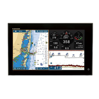
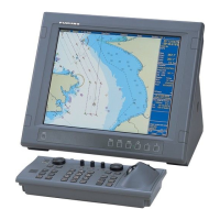
MONITOR
MU-155C/170C, etc.
VIDEO IN (CCD
CAMERA, MAX. 4)
LINE OUT
(SPKR, ETC.)
12-24 VDC*
2
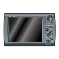
DISPLAY CONTROL
UNIT DCU12
CONTROL UNIT
MCU-001
AND/OR*
3
HUB-101
GPS NAVIGATOR
GP-320B/330B
AIS RECEIVER,
HEADING SENSOR or
EXTERNAL BUZZER
USB DEVICE
(MOUSE, KYBD)
NMEA 2000
(SENSOR, ETC.)
POWER SUPPLY UNIT
PSU-013*
1
: Standard Supply
: Optional Supply
: Local Supply
*1
Required with DRS25A
*2
See the table and figure below for
configurations for the PSU and rectifiers.
*3
Max. two units
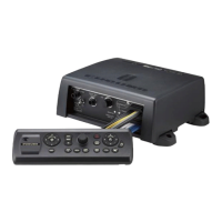
PROCESSOR UNIT
MPU-001
RADAR SENSOR
DRS4A/DRS6A/DRS12A/DRS25A
OR
RADAR SENSOR
DRS2D/DRS4D
FISH FINDER
(DFF series, ETR-6/10N, ETR-30N)
Matrix for radar model, PSU and rectifiers
DRS2D/4D/
4A/6A/12A
MFDBB
RU-1746B-2
DRS25A
MFDBB
PSU-013
DRS25A
MFDBB
PSU-013
Radar
Model
PSU Rectifier for
MFDBB
Rectifier for
PSU
Rectifier for
MFDBB+PSU
DRS2D Not
required
RU-1746B-2
DRS4D
DRS4A
DRS6A
DRS12A
DRS25A PSU-013* RU-1746B-2 RU-3424
* Standard supply with DRS25A.
12-24 VDC*
2
RU-1746B-2
12-24 VDC
2
LINE IN (MIC,
for future use)
DRS25A
DRS4A
DRS6A
DRS12A
RU-1746B-2
RU-3424
JUNCTION
BOX FI-5002
 Loading...