18
<Before Use>
As with all radio frequency transmissions,
the strongest area of signal transmission is from
the sides of the transmitter's antenna. As such,
the antenna should not be pointed directly at the
PRGHO,I\RXUÀ\LQJVW\OHFUHDWHVWKLVVLWXDWLRQ
easily move the antenna to correct this situation.
LED (Left)
Displays the "non-default condition" warning.
• Blinking
Power switch is turned on when any
condition switch is activated (in the ON
state).
LED (Right)
Displays the state of radio frequency
transmission.
• Off
Radio waves are in the OFF state.
• On
Radio waves are being transmitted.
• Blinking
Range check mode.
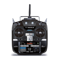
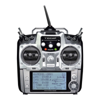
Monitor LED display
The status of the transmitter is displayed by
LED at the bottom left and right sides of the
"T12K" logo.
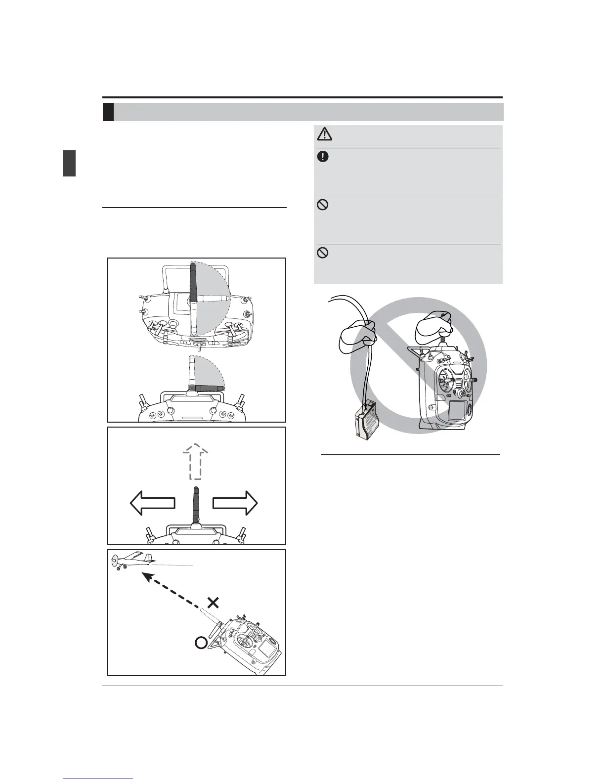
Rotating antenna
The antenna can be rotated 180 degrees and
angled 90 degrees. Forcing the antenna further
than this can damage it. The antenna is not
removable.
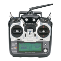
Caution
Please do not grasp the transmitter's
DQWHQQDGXULQJÀLJKW
Doing so may degrade the quality of the RF
transmission to the model
Do not carry the transmitter by the
antenna.
There is the danger that the antenna wire will break
and operation will become impossible.
Do not pull the antenna forcefully.
There is the danger that the antenna wire will break
and operation will become impossible.
Low power
High power High power
Itisnotgoodforthereto
beamodelonflightinthe
directiontipofanantenna.
Ifyouhaveatransmitter
atanangleofafigure,an
antennawillbegoodtouse
it,bending90degrees.
180°
90°
ŷƕƄƑƖƐƌƗƗƈƕŊƖŃŤƑƗƈƑƑƄ