HYHUVHURWDWLRQLIWKHFLUFOHLVVPDOOHURU
HUIRUPHGRQWKH
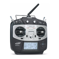
inside edge of the RTN button.
LVWRXFKLQJWKHVXUURXQGLQJFDVHSDUWV$VVXFKSOHDVH
PDNHVXUHWKDWWKHWLSRI\RXU¿QJHULVDFWXDOO\RSHUDWLQJWKH
ensorTouch™ might not react.
7KHWRXFKVHQVRUPLJKWQRWRSHUDWHE\
UHFH
SHUDWH\RXUWUDQVPLWWHUIURPWKHQRLVH
RXUKDQGVL]H
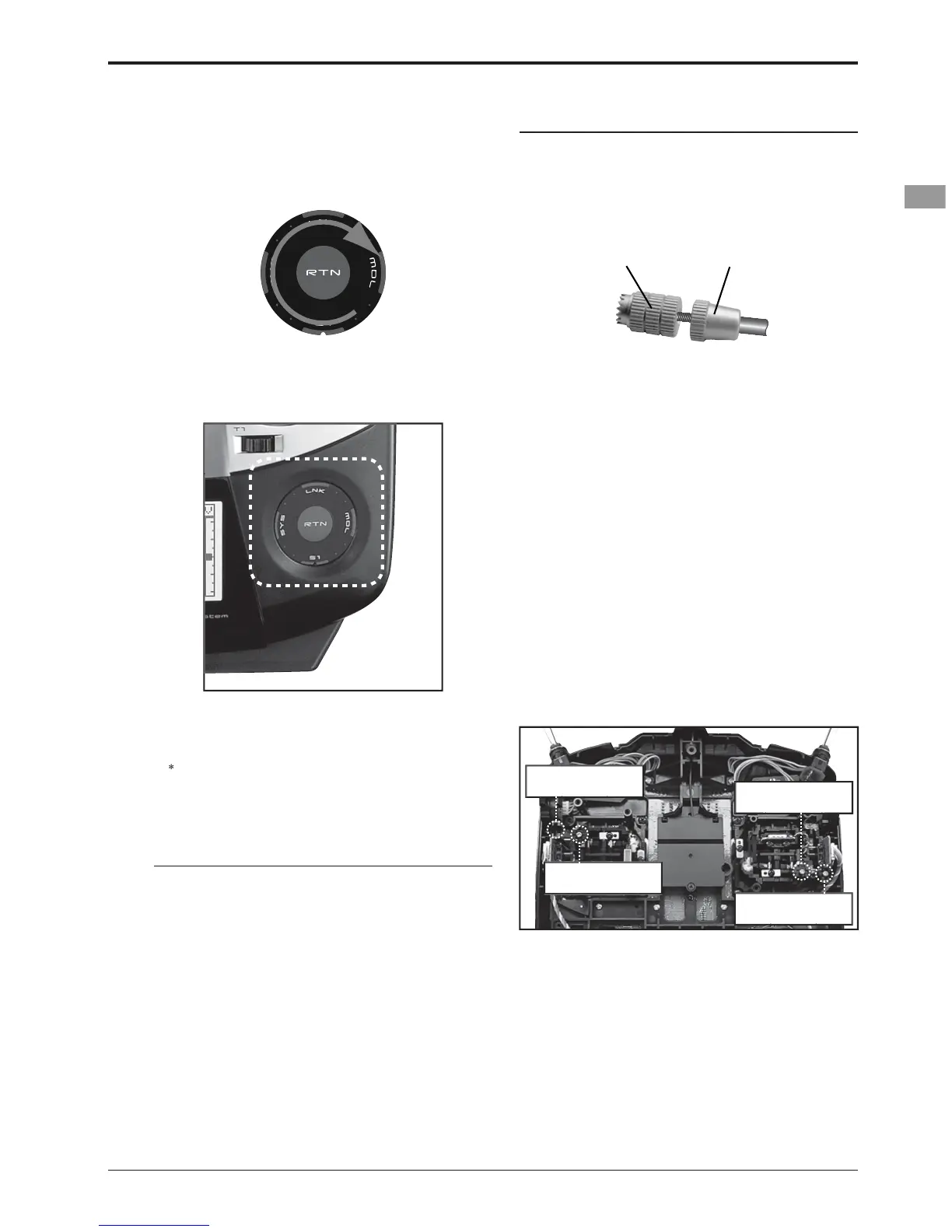
Lever Head
A
Lever Head
B
1
2. Turn the lever-head "A" clockwise as
ou hold
the lever-head "B" a
XVWPHQWRIVWLFNOHYHUWHQVLR
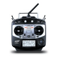
rst, Remove the battery cover on the
bottom o
tter. Next, unplug the
battery w
re and remove the battery
ease off the transmitter's rear case
Now you'll see the view shown in the fi
ng the
adjusting screw of the stick you want to
ad
ou loosen the screw too much,
the stick ma
erate because it is
caught