Page 25 of 32
Model 13352, 13362, and 13372 Addressable Amplified Speaker Assemblies Pub.: 43004-030A
d:\radio products-draft\gtc 43004\43004-030a\43004-030a.doc
06/05
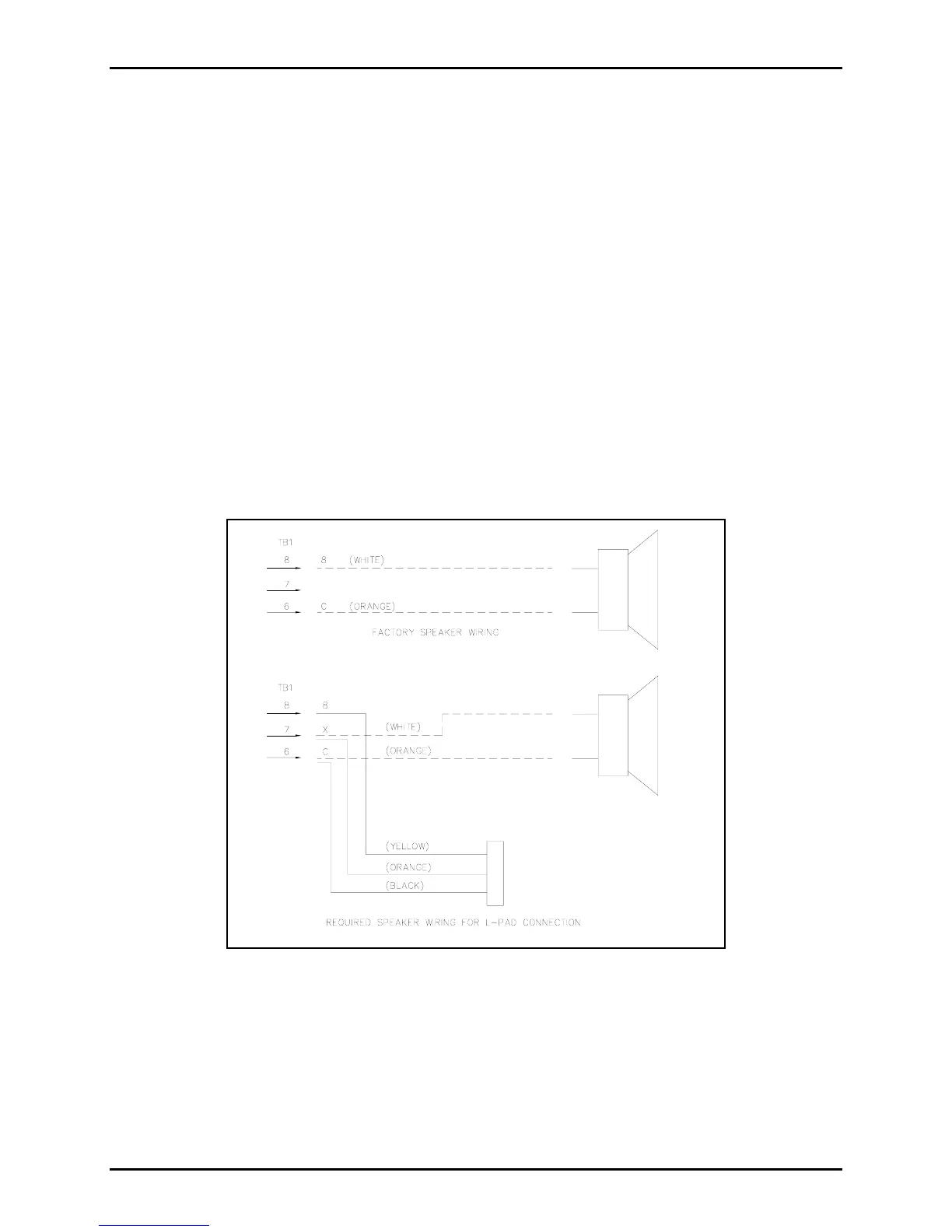
12506-001 Remote Volume Control Wiring Instructions
If the speaker requires local mechanical control of the output volume, an 8-ohm L-Pad volume control
(Part No. 12506-001) can be installed. The 12506-00l Remote Volume Control assembly is designed for
indoor installation but can easily be installed in a single gang outlet box, mounted inside a weatherproof
enclosure. Note that for full output volume range, the amplified speaker should be programmed for full
audio output power. Figure 5 below shows the wiring configuration needed for the use of the L-Pad
connection for local volume adjustment.
Refer to Figure 6 or Figure 7 to locate TB1, the 11-point connector noted in the Figure 5. The connector
numbering begins with position 1 at the bottom and ends with position 11 at the top.
1. Open the speaker housing.
2. Remove the white wire from TB1-8 and reroute the wire to TB1-7.
3. Connect the yellow wire from L-Pad to TB1-8.
4. Connect the orange wire from L-Pad to TB1-7.
5. Connect the black wire from L-Pad to TB1-6.
Figure 5.
With the rear section securely mounted and field wiring in place, reattach the wiring harness’ quick-
connect fastons to the speaker. Reconnect the 11-point connector to the PCBA and route the wires
through both nylon ties. Re-twist the nylon ties to secure the wires. Refer to Figure 6 and Figure 7 for
wire routing. Assemble the speaker sections and tighten front panel screws to 16 to 20 in-lbs. of torque.
N
OTE: Be careful not to pinch wiring between the front and rear speaker sections when securing
them together.
 Loading...