Page 30 of 32
Model 13352, 13362, and 13372 Addressable Amplified Speaker Assemblies Pub.: 43004-030A
d:\radio products-draft\gtc 43004\43004-030a\43004-030a.doc
06/05
Radio Connector Pinout
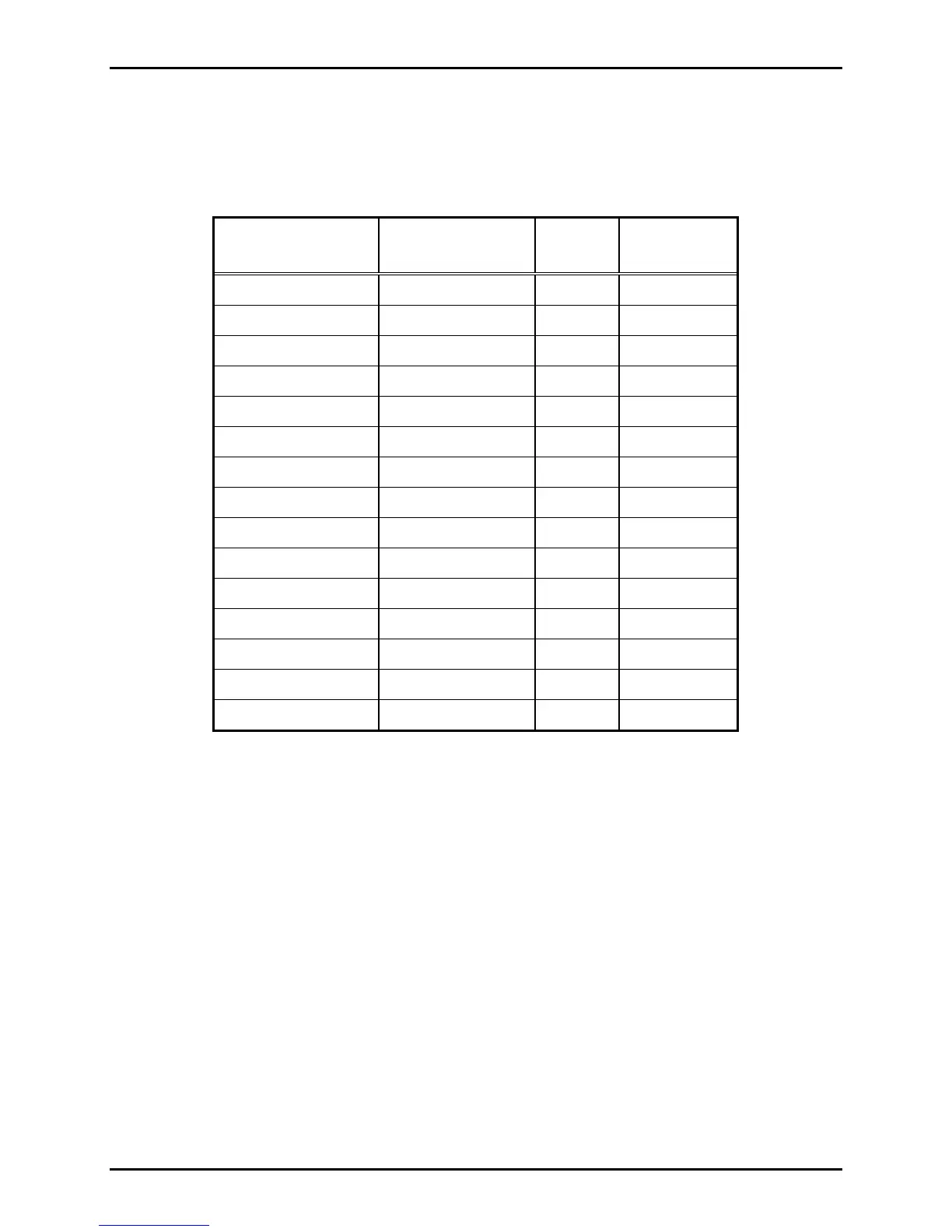
The pin-out for the radio connector on the speaker half of the assembly is described below. The
numbering orientation is shown in Figure 8.
Addressable Amplified Speaker’s Radio Connector Pin-Out
Position
DB15 Connector
Position
8-Pin Connector Color
Radio
Reference
Pin 1
Pin 2
Pin 3
Pin 4
Pin 5
Pin 6 Pin 5 Black Power
Pin 7
Pin 8
Pin 9
Pin 10
Pin 11
Pin 12 Pin 2 Black Audio
Pin 13 Pin 6 Black Carrier detect
Pin 14
Pin 15 Pin 4 Black Ground