Page 28 of 32
Model 13352, 13362, and 13372 Addressable Amplified Speaker Assemblies Pub.: 43004-030A
d:\radio products-draft\gtc 43004\43004-030a\43004-030a.doc
06/05
Hardware Configuration
Jumpers
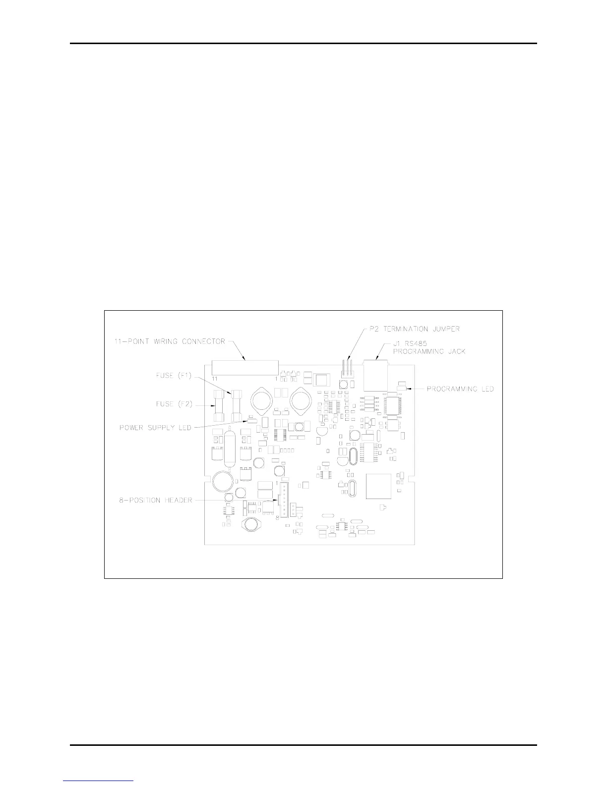
The Model 13352 P2 termination jumper setting configures the unit for 600-ohm (P2-2 to P2-3) or 15 k-
ohm (P2-1 to P2-2) termination. For Models 13362 and 13372, this jumper has no function. This jumper
is accessible by separating the rear section of the speaker from the front section. Refer to Figure 8.
Fuses
There are two fuses located on the PCBA. Fuse F1 is the external power fuse, which limits the current
draw from the external power supply. Fuse F2 is the battery fuse, which limits the current draw from the
battery. Refer to Figure 8.
LEDs
Two indicator LEDs are located on the PCBA, but are visible only on the speaker’s front section when the
assembly is opened. The power supply LED is activated when the unit is receiving external power. The
programming LED indicates when CARD Suite programming has been initiated.
Figure 8. Amplified Speaker Assembly PCBA