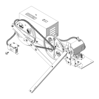
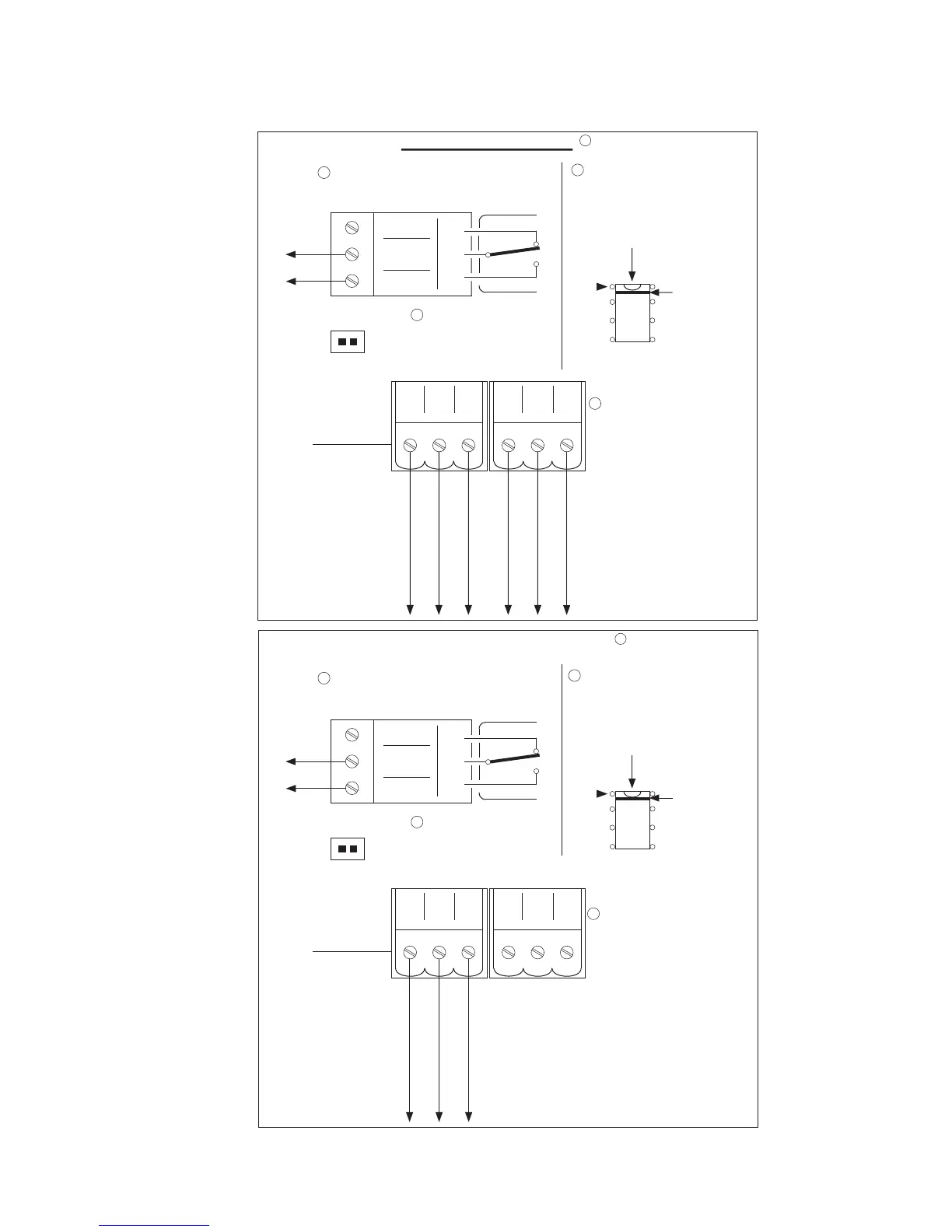
C. Wiring diagram:
G.A.L. Manufacturing Corporation December, 2007
TRI-TRONICS (Leading Edge)
Make sure that the reopen contact
of the MOVFR is connected to the
main controller.
NC
COM
NO
RE-OPEN
Insert enable chip
DPPC-0001N (U5)
into the socket.
Make sure the red
stripe is positioned
in pin 1 as shown.
U5
Red Stripe
JUMPER
JP1
Remove
jumper
JP1
Connect the interfacing
cable to the TRI-TRONICS
detector edges (DPTT).
CN5 CN4
+V
SE
LC
OV
+V
SE
LC
OV
RED
WHITE
BLACK
R
4
2
3
1
FORMULA SYSTEMS
Make sure that the reopen contact
of the MOVFR is connected to the
main controller.
NC
COM
NO
RE-OPEN
Insert enable chip
DPPC-0001N (U5)
into the socket.
Make sure the red
stripe is positioned
in pin 1 as shown.
U5
Red Stripe
JUMPER
JP1
Remove
jumper
JP1
Connect the interfacing
cable to the Formula
Systems detector edges
(DPFS).
CN5 CN4
+V
SE
LC
OV
+V
SE
LC
OV
R
4
2
3
1
GRN/YEL
BLACK/2
BLACK/1
GRN/YEL
BLACK/2
BLACK/1
 Loading...