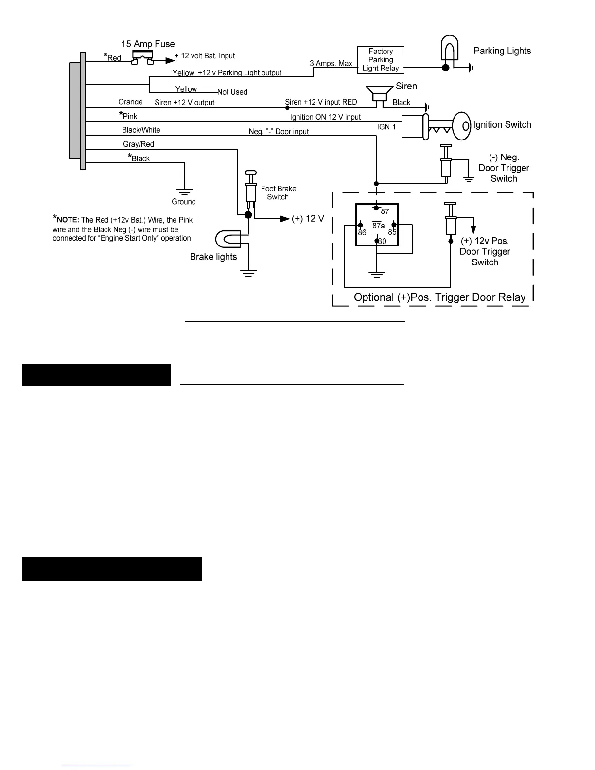
C3: 7 PIN WIRING HARNESS DIAGRAM
button can be surface mounted in a
location on the dash or can be mounted using
the supplied adjustable bracket for mounting under the dash or on the console.
is to be used on the back side of the switch with both mounting methods. Make certain that the
mounting surface is thoroughly cleaned with
to remove any dirt, grease or
DO NOT use acetone, MEK, lacquer thinner or any other harsh chemicals as they
will destroy paint, vinyl and plastic
The adhesive will not come loose or degrade as long as the surface has
e back of the button first.
If you choose to mount the button
with the wire hidden behind the button then d
location where the small wire and connector can be fed through the dash
Connect the White 3 terminal connector to the module. The connector is indexed so that it can only be
installed in one direction.
Recheck all electrical connections to be certain they are connected in the proper locations
ll connections are wrapped with a good quality electrical tape or shrink tubing
Connect all 4 module connectors to the module. The module should be secured
Attach the R1/R2 relay pair under the dash and secur
onnect the battery and thoroughly test all starting functions. Make certain that the vehicle can not be
started while it is in any gear except Neutral and/or Park
. The alarm functions will not function until the key FOBs have been taught
rogram the module to the functions that you desire following
“Programming Function Set Up
 Loading...