EasyManua.ls Logo

Gallo Tech GTS-3RS - Page 13

Default Icon
16 pages
Print Icon
To Next Page IconTo Next Page
To Previous Page IconTo Previous Page
Loading...
© Copyright
Gallo Technologies
. All Right Reserved
-
13
-
0
615
1
5
V54RS
Power Door
Lock
Connections:
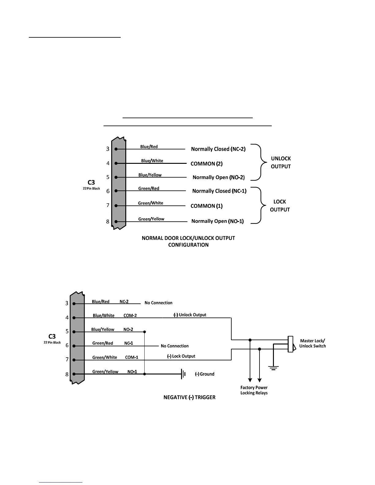
Determine the Door Locking/Unlocking circuitry that your vehicle is equipped with. Fig.
2
shows th
e door lock/unlock
output relay
& Pin number
configuration of
the
C3
Control Module
connector
.
The majority of vehicles come
equipped with
either Neg (
-
)
Fig.
3
or Pos. (
+) Fig.
4
Trigger circuits. Find the location of the appropriate circuitry for
your ve
hicle (Make, Model, Year Diagrams can be found on our web site at www.GalloTech.com) If the Trigger wire
is 0v when the Lock/unlock switch is depressed then you have a Neg. (
-
) trigger
(Fig.
3
). If the trigger wire is +12v
when depressing the Lock/unlock s
witch then you have a Pos
. (
+) Trigger (Fig
4
). For Pre
-
’95 Audi or Mercedes
Benz vacuum motor operation use Fig.
5
. For Reverse Polarity applications, were the
lock and unlock wires rest at
Negative Ground,
use Fig.
6
.
C
3
:
22
PIN WIRE HARNESS DIAGRAMS:
Only
Door Locking/Unlocking
Pins #’s shown below
Figure
2
Figure
3