Use and Maintenance Manual – Pressure-sensitive bumpers type GSBPS 8/35
4 Description and working principle
Definition:
GAMMA SYSTEM PRESSURE-SENSITIVE BUMPER is a “safety device" used as an "electro-sensitive
protective device designed to detect persons or parts of person. It is described in Annex IV of the Machinery
Directive 2006/42/CE. In particular, it is classified as a "safety device equipped with a sensor, capable of
detecting a pressure, and a control circuit having a verification function according to the specified category
and an output interface”. The sensitive surface undergoes a local deformation which actuates the sensor”.
It consists of two essential parts:
A PRESSURE-SENSITIVE SENSOR
A CONTROL UNIT
Working principle:
When the pressure-sensitive bumper is actuated by an external force, after a defined deformation called
“pre-travel”, the two parts of the plastic material come into contact and the circuit makes. The change in state
of the internal sensor (from NO to NC) is processed by the control unit (sensor control device) which sends a
stop signal to the machine thereby eliminating the danger situation. After the pre-travel, the bumper still
allows for an extra depression called “over-travel” during which the hazardous movement is stopped.
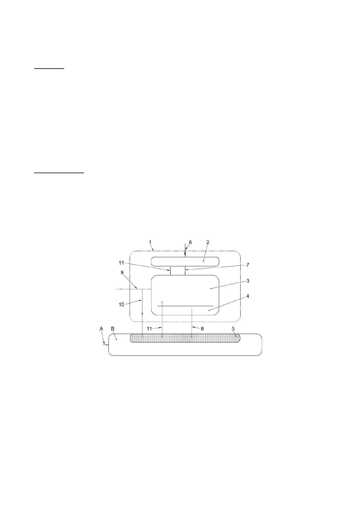
Legend
1 Pressure-sensitive bumper
2 Sensor/s
3 Control unit (can be located inside the enclosure of the machine control system or be an integral part of the control
system itself).
4 Switching device(s) for the output signal (can be installed inside the enclosure of the machine control system or it can
be an integral part of the control system itself
5 Part of the machine control system for processing the output signal of the pressure-sensitive bumper
6 Actuation force
7 Sensor output signal
8 Signal for active state (ON)/inactive state (OFF)
9 Signal for manual reset (if appropriate, alternative to A)
10 Reset signal from the machine control system (if appropriate)
11 Monitoring signals (optional)
A Signal for manual reset of the machine control system (if appropriate, alternative to 9))
B Machine control system(s)
 Loading...