13–9/10–641 Page 19
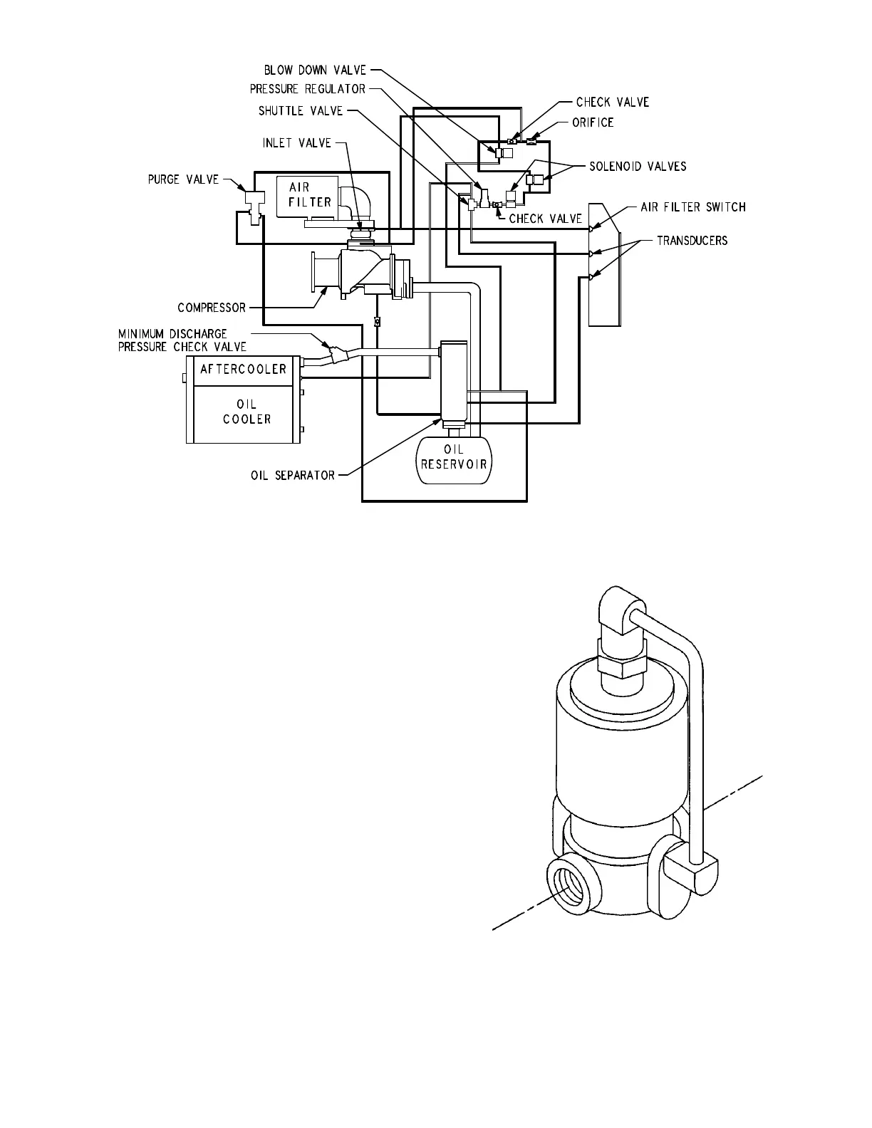
FIGURE 4–1 – SCHEMATIC TUBING DIAGRAM
211ECM797–B
(Ref. Drawing)
Blowdown Valve (FIGURE 4–2) – This valve normal-
ly is used for control functions, but also serves to relieve
reservoir pressure following a shutdown. The blow-
down valve is a two–way solenoid valve which is piped
into the oil reservoir outlet ahead of the minimum pres-
sure valve. When the solenoid is de–energized, the
valve opens and the coolant system is blown down.
When the solenoid is energized, the valve closes to al-
low the coolant system to pressurize. A control air
check valve is provided to ensure that the inlet valve is
closed during blowdown.
Oil Level Gauge (FIGURE 1–6, Section 1, page 3) –
This gauge is located on the oil reservoir and indicates
the oil level. See section 5 for information on how to
correctly read the gauge and proper lubrication.
Minimum Discharge Pressure/Check Valve
(FIGURE 4–3, page 20) – An internal spring–loaded
minimum pressure valve is used in the final discharge
line to provide a positive pressure on the coolant sys-
tem of the compressor even if the air service valve is
fully open to atmospheric pressure. This valve also
functions as a check valve to prevent back flow of air
from the shop air line when the unit stops, unloads, or
is shut down.
FIGURE 4–2 – BLOWDOWN VALVE



 To Next Page