13-18-601 Page 56
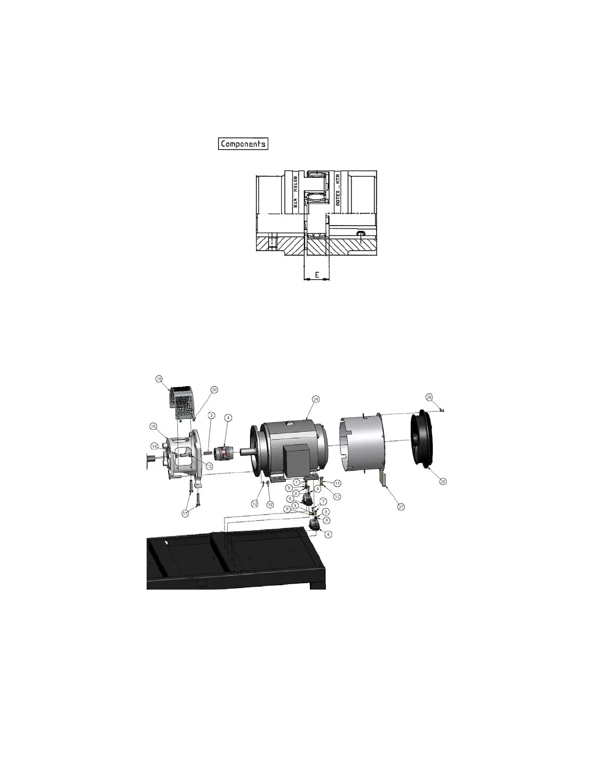
• After engaging each hub on the matching recesses of the coupling element, check that the gap
between the hub flats (see dimension “E” on Figure 8-2) is no less than 1.1 in (28mm). A
smaller gap will produce abnormal wear of the element by friction and excessive thermal
expansion – the latter could cause compressor damage by axially displacing the input shaft.
Make sure that keys are in proper alignment with key-ways on hubs.
Figure 8-2 – COUPLING ELEMENT
4. For hub-to-shaft interference fit hubs, main drive motor removal is necessary:
Figure 8-3 – MOTOR REMOVAL HARDWARE
• Remove coupling guard (19) by removing four bolts
• Remove two bolts securing [cooling fan] support (27) to baseframe (2)
• Remove four bolts securing [main motor] rear support to baseframe (2)
• Remove upper two bolts securing main motor (24) to adaptor (16) and replace with longer
versions provided with package – there should be 3-in gap between bolt head and adaptor.
300CGD810-
(Ref. Drawing)




 To Next Page