13-18-601 Page 49
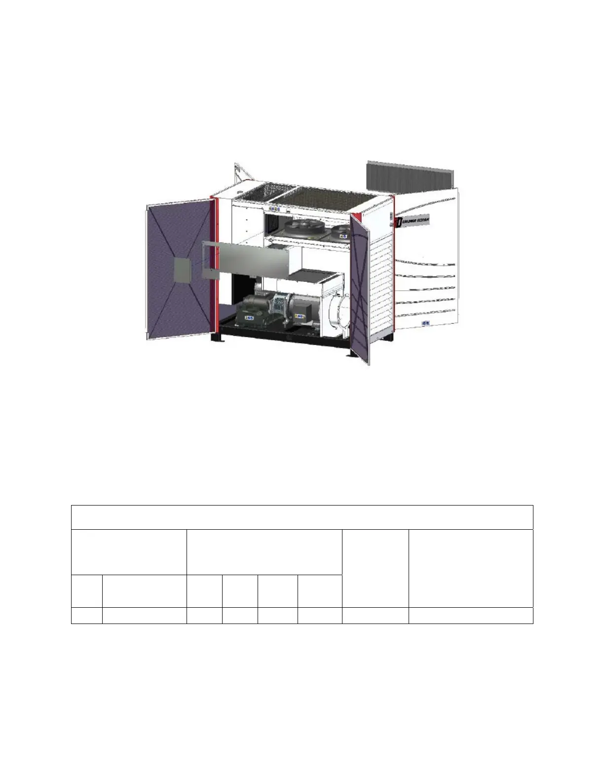
5. Inspect core area. If blocked with debris, use a moderate (e.g., 100psi) source of compressed air
and/or water while directing nozzle (pointed through core to inside) to dislodge debris and clean.
Vacuum (applied from inside) can also be employed to clean the heat exchanger cores.
6. Remove all loose debris and water from cooler box after cleaning process is complete.
7. Re-attach cooler housing side covers with provided fasteners and re-install enclosure door panels.
Figure 6-2 – COOLER HOUSING SIDE COVERS
WATER-COOLED HEAT EXCHANGERS – Optional water-cooled cores (brazed-plate type) are
available. Both core are of a counter-current and cross-flow design. The cooling water is fed to the cores
in a series arrangement – it passes through the air core first and proceeds through the oil core before
exiting the package. Please refer to Figure 6-3 for estimates of requirements.
AIR & OIL COOLER (Series Water Piping)
Water flow requirements at
various inlet water temperatures
(gpm)
KW Model
60° F 70° F 80° F 90° F
Maximum
Water Flow
(gpm) *
Approximate (total) water
pressure drop @ 90° F
water flow
(psi)
All VS45-70A 8.5 12.8 25.6 40 40 20
* Flows exceeding "Maximum Water Flow" will cause severe erosion and will void unit warranty.
Figure 6 3 – WATER-COOLED HEAT EXCHANGER COOLANT REQUIREMENTS
 Loading...