Garmin G5 Electronic Flight Instrument Part 23 AML STC Installation Manual 190-01112-10
Rev. 21
Page 34
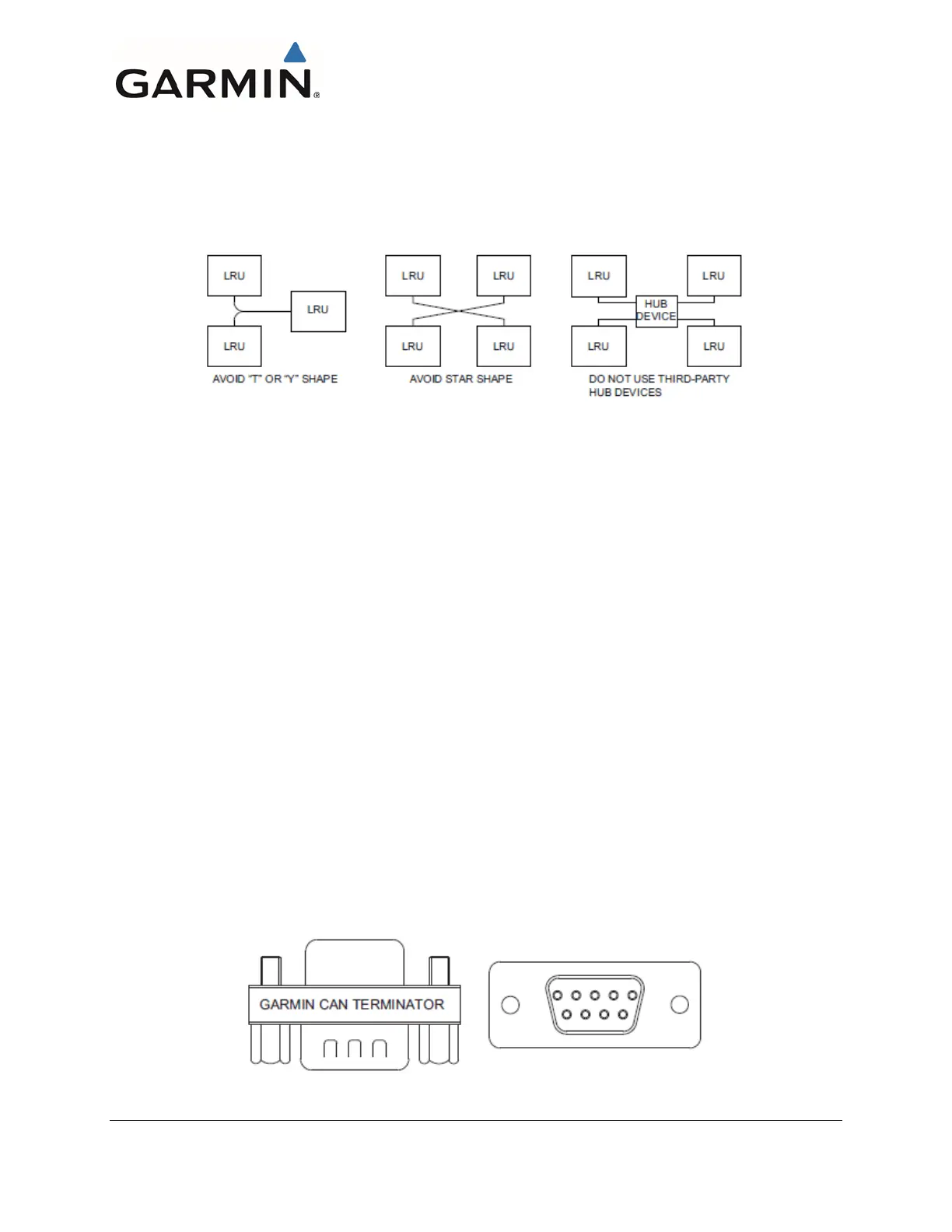
through short “stub” or “node” connections (Figure 3-2). The length of each node connection should be
3 inches or less, the maximum allowed distance from a splice to a connector, unless otherwise specified.
Multiple devices must not connect to the CAN bus backbone at the same point. Rather than splicing two
or more stub node connections together, the CAN bus should instead be daisy-chained from one device
to the next (Figure 3-2).
Figure 3-3 Incorrect CAN Wiring Example
3.4.5.2.2 CAN Bus Wiring
CAN bus wiring must only be connected to Garmin LRUs. All new installations must use 120Ω CAN
bus cable (see Section 3.2.1) or shielded twisted-pair cable, MIL-C-27500. The shields for each CAN
bus wire segment must be interconnected, forming a continuously connected shield from one end of the
CAN bus to the other end of the CAN bus. The CAN bus shield must always be grounded to the device
connector backshells on all devices connected to the CAN bus.
3.4.5.2.3 CAN Bus Termination
At each of the two extreme ends of the CAN bus backbone, a 120Ω resistor is installed to terminate the
bus. Termination resistors are provided either via termination adapters that plug into an LRU’s CAN
connection, a resistor internal to the LRU or a 120Ω resistor installed into the wiring harness at a G5 if
the G5 is the end of the CAN bus backbone.
• The G5, GMU 11, and GAD 13 connector kits provide a 9-pin termination adapter that provides
termination when attached to the device’s main connector. The termination adapter contains a
120Ω resistor that is connected between pins 1 and 2 (Figure 3-4).
• The GAD 29/29B contains a 120Ω resistor inside the unit that provides termination when the
two CAN TERM pins are connected together (Figure 3-5). Alternatively, the GAD 29/29B can
be terminated externally using a termination adapter, Garmin P/N 011-02887-00 (Figure 3-4).
• If a G5 is installed using shielded twisted-pair cable, MIL-C-27500 and is at the end of the CAN
bus backbone a 120Ω resistor is installed in the wiring harness (Figure 3-6).
Figure 3-4 CAN Bus Termination (011-02887-00) for G5, GMU 11, and GAD 13

 Loading...


