INSTALLATION OF STANDALONE TWIN
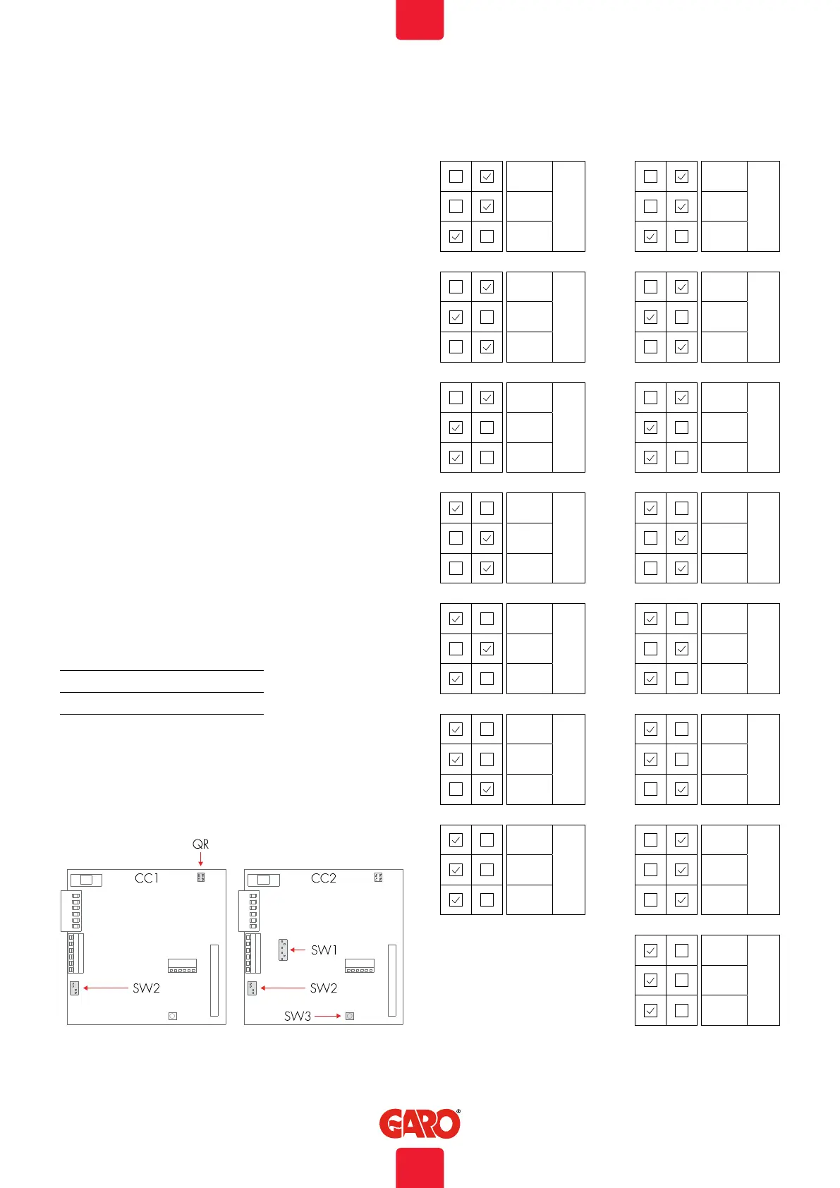
5. With dip 1-3 on SW2 on both CC1 and CC2, you can (when
needed) reduce the charge current (A) separate for left/right hand
side of the TWIN. Available range is 6A – MAX32A, see (figure
8). This is normally not necessary to do at a standard installation.
Note: it is ok to set different value for left and right hand side.
SW2 on CC1 controls left hand side and SW2 on CC2 controls
right hand side.
Dip switch SW2 is located at bottom left hand side on both CC1
and CC2, see (figure 9).
Note: Dip 1-3 SW2 settings on both CC1 and CC2 MAX
Ampere (A), see (figure 8).
6. Install the electrical supply cable to terminals L1-L3, N , PE.
Note: TWIN is equipped with double terminals that makes it easy
to forward the supply cable to another TWIN, see (figure 9).
7. Fill in the serial number in the Guarantee form. See QR code
label at upper right corner of CC1, see (figure 9).
SW1 SW2
ON OFF ON OFF
3
3=OFF
16A
3 3=OFF
6A2
2=OFF 2 2=OFF
1
1=ON 1 1=ON
3
3=OFF
20A
3 3=OFF
10A2
2=ON 2 2=ON
1
1=OFF 1 1=OFF
3
3=OFF
25A
3 3=OFF
13A2
2=ON 2 2=ON
1
1=ON 1 1=ON
3
3=ON
32A
3 3=ON
16A2
2=OFF 2 2=OFF
1
1=OFF 1 1=OFF
3
3=ON
40A
3 3=ON
20A2
2=OFF 2 2=OFF
1
1=ON 1 1=ON
3
3=ON
50A
3 3=ON
25A2
2=ON 2 2=ON
1
1=OFF 1 1=OFF
3
3=ON
63A
3 3=OFF
29A2
2=ON 2 2=OFF
1
1=ON 1 1=OFF
3
3=ON
32A2
2=ON
1
1=ON
SW2 MAX Ampere
TWIN 3,7 kW = MAX 16 A
TWIN 7,4 kW = MAX 32 A
TWIN 11 kW = MAX 16 A
TWIN 22 kW = MAX 32 A
(figure 8)
(figure 9) (figure 10)
7
EN


 To Next Page