USER GUIDE - MC3001
6
Working principle:
In the non-actuated state (such as shown in figure 1), the motor drives the pump which continuously supplies the
circuit with oil. The control valve (4) is in position middle (see figure 1). The oil is in a closed circuit and returns to
the oil tank (8).
During crimping, the control valve (4) is in the RH position. The connection P to B on the control valve (4) is estab-
lished. The crimping chamber is supplied with oil. When pressure is equal or greater than the required
pressure, excess oil is returned to the oil tank (8) via the pressure limiter (2).
Oil in the retraction chamber is evacuated to the oil tank (8) via the control valve (4) from A to T.
During die retraction, the control valve (4) is in the LH position. The connection P to A on the control valve is estab-
lished. The die retraction chamber is supplied with oil. A system in the bell housing allows the pressure to reduce
during the return. Oil in the crimping chamber is returned to the oil tank (8) via the connection B to T on the control
valve (4). The volume of oil in the crimping chamber being larger, oil is also evacuated via the pilot valve (3).
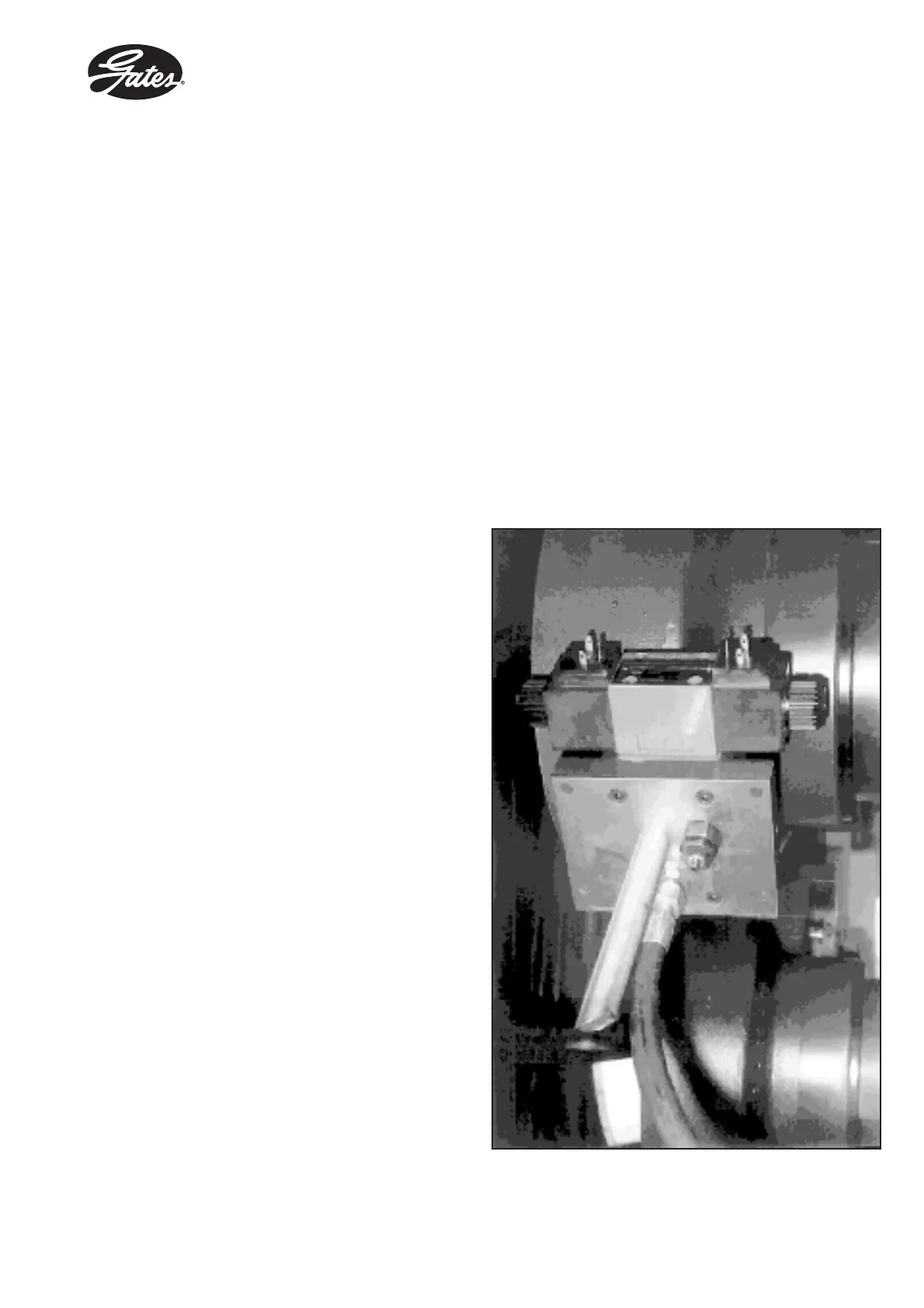
Figure 2 : View of drilled block.