Instructions for SW200DC
www.gatexpertstore.com
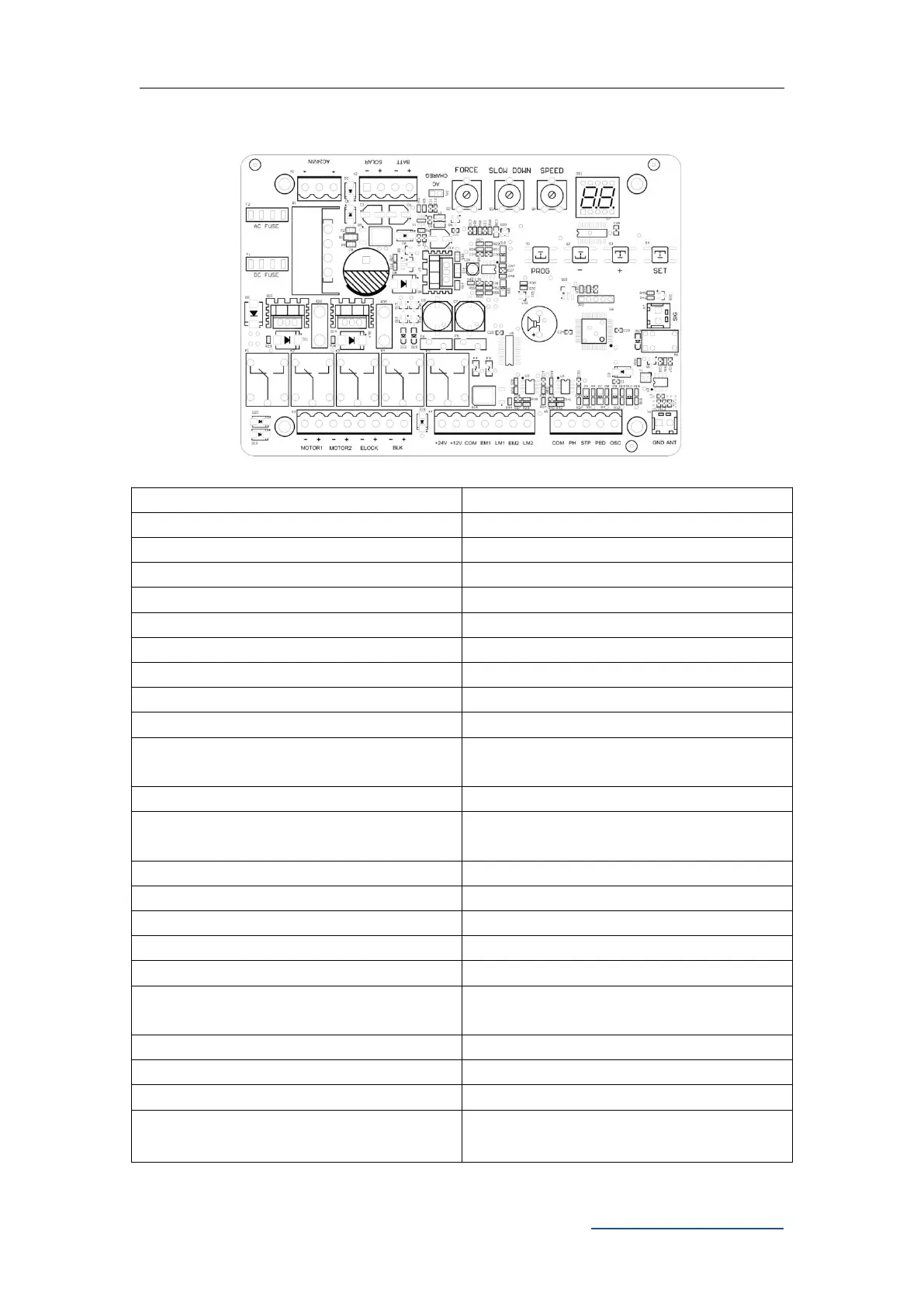
9.2 Control Board Drawing and Instructions
Figure 12
Alarm Lamp Output (Note: pay
attention to the negative and positive.)
12V Output Positive (No output under
dormant state)
Motor1 Hall Sensor Power Output
Motor1 Hall Sensor Limit Signal Input
Motor2 Hall Sensor Power Output
Motor2 Hall Sensor Limit Signal Input
Photo Sensor Input Active
Single Gate/Pedestrian Mode Input
Active
Single Channel Input Active
The signal is normally closed only after
the door is in place