Page 16 of 25
5.4 12Vdc Low Voltage Signal Port
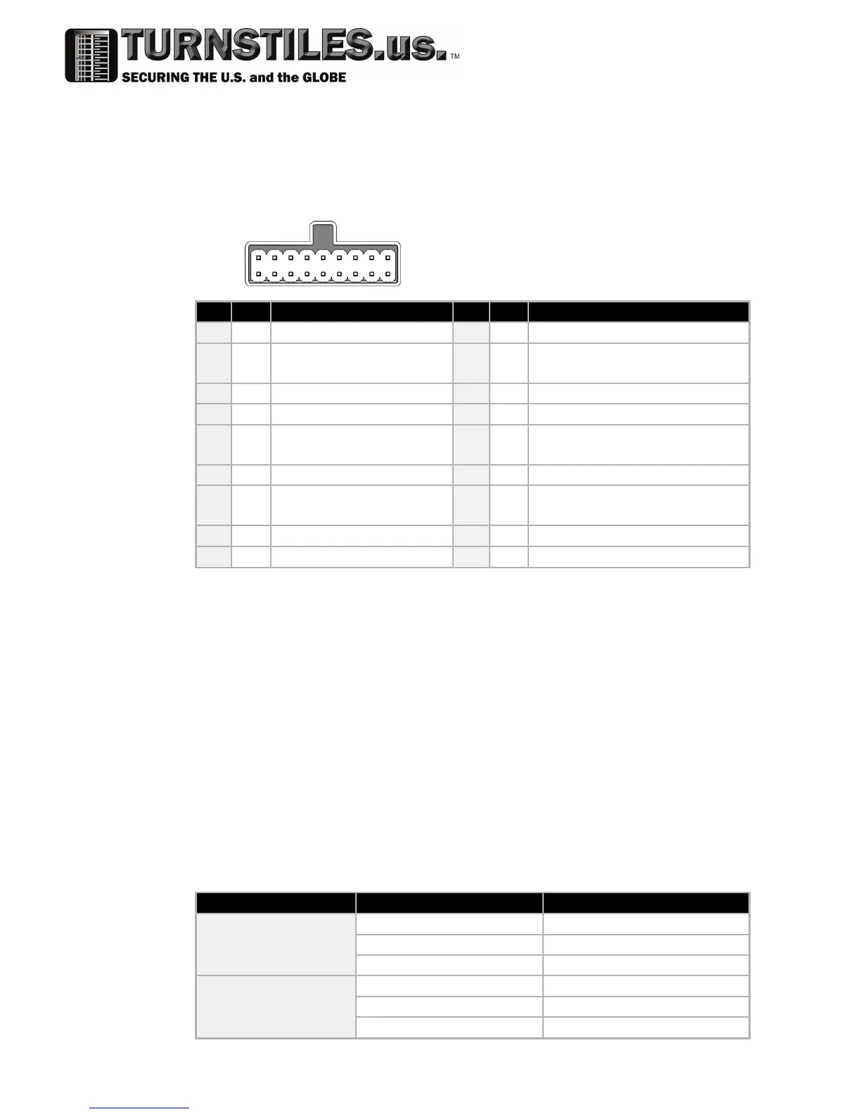
5.4.1 18-pin Connector Details
Recommended mating connector: TE Connectivity / Amp - 5-102398-7 - Connector,
Header, IDC, 2.54mm, 18way
Pin Function Pin Function
1 Out Credit Pulses
(1)
10 Out Alarm
2 Out Ready To Send for Serial
Mode
11 12 Volt DC Input
(6)
3 In Serial / Pulse Select Line 12 In Enable Validator
(3)(2)
4 DC Ground 13 Out Power for Alarm LED
5 Out Transmit (TTL level
RS232)
14 In Serial – Ready to Send or
Receive (TTL level RS232)
6 Out Parallel Vend Channel 1 15 Out Parallel Vend Channel 5
7 Out Parallel Vend Channel 2 16 In Alternate Receive (TTL level
RS232)
(5)
8 Out Parallel Vend Channel 3 17 Out Parallel Vend Channel 6
9 Out Parallel Vend Channel 4 18 In Parallel Escrow Control
(4)
Notes:
1. All outputs pull the pin to ground when active
2. When using Low Voltage Enable input on this connector, do not connect High
Voltage Enable pins to avoid conflicts in the control logic. See table below
3. The Enable Validator input can be configured for Active Low (validator is in
service when the input is pulled to ground) or Active High. If the ST1C is fitted
with a DIP switch, this input can be over-ridden by the “Always Enable” switch.
4. The Escrow Control Input is always configured as Active Low
5. For serial protocols, the data line can be connected to either pin 14 or 16
6. The 12 Volt DC input is provided for low voltage operation only.
5.4.2 Low Voltage Enable
The logic for the Enable Validator input on pin 12 is:
Condition Input status Validator Status
Active Low
Low Enabled
Disconnected Inhibited
High Inhibited
Active High
Low Inhibited
Disconnected Inhibited
High Enabled
1
10
9
18
View looking at the validator