EasyManua.ls Logo

GBA ST1C - User Manual

GBA ST1C
30 pages
Print Icon
To Next Page IconTo Next Page
Loading...
GBA Global Bill Acceptors
GBA ST1C Operation Manual
Page 1 of 30
Astrosys International Ltd
GBA ST1C Operations manual V1_4
GBA ST1C
Operation Manual
This document is the c
opyright of Astrosys International Ltd. and may not be reproduced in total or in part
by any means, electronic or otherwise, without the prior written consent of Astrosys International Ltd.

Questions and Answers

Summary

Introduction to GBA ST1 C

Product Overview and Features

Provides an introduction to the GBA ST1C and lists its key features for various applications.

Product Information

General Specifications

Details bill insertion, dimensions, acceptance rate, cycle time, supported protocols, power, and environmental range.

Product Architecture Details

Product Assembly Components

Identifies and describes the main chassis, bottom sensor assembly, bill cassette, and faceplate/note guides.

Cassette Fitting and Removal

Cassette Capacity and Security

Details the standard 300-note cassette, its locking mechanism, and access to stacked bills.

Sensor Assemblies and Faceplates

Bottom Sensor Assembly

Details the bottom sensor assembly, including tension rollers and access latch.

Note Guide and Faceplate Variations

Explains the two available note guide sizes (USD, CAN) and faceplate options for stacking configurations.

Interface Cable and Coupon Sensor

Interface Cable Assembly

Details the 20-pin interface connector used for communication to a host machine.

Bar-coded Coupon Sensor Functionality

Explains the sensor for detecting and reading barcodes on printed coupons.

Interface Protocols

NAMA MDB Protocol Configuration

Details requirements for using the NAMA MDB interface, including power regulator and opto-isolators.

ccTalk Protocol Configuration

Information on the ccTalk interface, including an alternative 20-pin harness option.

USB Interface Configuration

Describes the optional USB interface for PC connection and data transfer using specific protocols.

Software Configuration Methods

On-board Push Button Configuration

Explains how to use the on-board push button for programming modes like note enable and disable.

Enable Note Configuration Procedure

Step-by-step guide to enabling a specific note denomination via the push button.

Advanced Software Configuration

Disable Note Configuration Procedure

Step-by-step guide to disabling a specific note denomination via the push button.

Programming Card Configuration

Procedure for configuring the unit using a programming card, including requirements and success indicators.

Re-Calibration Procedure

Steps for performing periodic recalibration of the validator, including required equipment.

Calibration Error Codes

PC and USB Configuration Tools

PC Based GBA Tools Overview

Details PC based software like GBA Talk and GBA Service for configuration and diagnostics.

GBA Talk PC Software Configuration

Procedure for configuring the validator using GBA Talk PC software, including connection and steps.

USB Mass Storage Device Configuration

Explains reprogramming a unit using a USB Mass Storage Device (memory stick).

Connecting a USB Mass Storage Device

Guide on connecting a USB memory stick for reprogramming, including adaptor cable requirements.

File Location on USB Device

Information on where to place firmware, dataset, and configuration files in the root directory of a USB device.

USB Update Process and Errors

USB Update Sequence of Events

Describes the process the validator follows when detecting and loading files from a USB device.

USB Download Error Codes

Table of LED error codes displayed by the diagnostic LED during USB download failures.

Software Configuration Options Overview

Supported Interface Options

Lists the various interface protocols that the GBA ST1C can be configured to use.

ccTalk Encryption Key Reset Procedure

Procedure for resetting ccTalk encryption keys using a specific programming card.

Escrow Time Out Period Setting

Details the configurable escrow time out period for parallel interfaces.

Low Power Mode Setup

Explains the low power mode, its benefits, and how to enable it.

Illuminated Note Guide Patterns

Electrical Interface Specifications

Power Requirements

Details voltage and power supply specifications for the 20-pin and optional MDB connectors.

Signal Interface Specifications

Specifies voltage levels, current limits for open collector outputs and digital inputs.

20-pin Connector Electrical Specifications

Provides detailed electrical specifications for the 20-pin interface connector.

MDB 6-pin Connector Electrical Specifications

Outlines the electrical specifications for the optional MDB 6-pin connector.

USB Port Compliance and Type

States compliance with USB 2.0 and the type of mini-AB socket used.

Low Power Mode Operation

Low Power Mode Electrical Connections

Specifies the correct 12VDC pin connections for enabling Low Power Mode.

Interfaces Supported in Low Power Mode

Lists the interface protocols that are compatible with the Low Power Mode feature.

Low Power Mode Operational Behavior

Explains how the unit wakes up, returns to sleep, and interacts with the host in Low Power Mode.

Electrical Connections

20-pin Connector Pinout and Interface Mapping

Details the pinout of the 20-pin connector and signal mapping for various interfaces.

Maintenance Procedures

Cleaning the Validator Note Path

Provides step-by-step instructions for cleaning the note path using recommended solutions and precautions.

Clearing a Note Jam

Diagnostics and Troubleshooting

Validator Diagnostics Overview

Explains the use of the tri-coloured Status LED for communicating validator status and diagnostics.

Status LED Operational Indicators

Details the meaning of different LED states (standby, active, program modes) for operational status.

Illuminated Note Guide Status

Describes the note guide's illumination status, particularly when the unit is out of service.

Note Reject Status LED Codes

Lists common causes for note rejection and the corresponding flash codes shown on the Status LED.

Troubleshooting Common Problems

Dimensional Drawings

Upstacker Configuration Dimensions

Provides detailed dimensional drawings and measurements for the upstacker version of the GBA ST1C.

Downstacker Configuration Dimensions

Provides detailed dimensional drawings and measurements for the downstacker version of the GBA ST1C.

Revision History

Disclaimer

Regional Offices

Overview

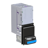
The GBA ST1C is an integrated bill validator and stacker designed for amusement and vending applications, though it is also suitable for parking and internet kiosks. It is manufactured to ISO 9001 standards and is CE, UL, C-Tick, and ROHS compliant.

Function Description:

The GBA ST1C's primary function is to validate and stack paper currency. It incorporates "Sense Technology" for bill discrimination and can accept up to 32 different bill denominations with 4-way insertion. The unit can be configured for either up or down entry stacking. A single cassette option provides a bill capacity of 300 notes. For enhanced security, tamper-evident, lockable cassette options are available. The device also features integrated optical anti-string protection to prevent fraudulent activity. An optional bar code reading function allows it to detect and read barcodes on printed coupons, particularly those printed thermally with green light. The content of the barcode can be read back as a text string using ccTalk and GBA BSCP protocols. The validator supports multiple interfaces, including Pulse, Parallel, ccTalk® (plain & encrypted), bi-directional serial (“RS232”), NAMA MDB, SSP, and JVI/VCCS.

Important Technical Specifications:

  • Bill Insertion: Up to 32 bill denominations with 4-way insertion.
  • Bill Dimensions: Accepts bills from 62 to 70mm wide and 120 to 160mm long.
  • Bill Acceptance Rate: Greater than 95%.
  • Cycle Time for Validation and Stack: Typically less than 3 seconds.
  • Power Supply: 12Vdc +/-10% regulated for the 20-pin connector. An optional MDB 6-pin connector and power regulator support 20 to 50 Volts DC.
  • Power Consumption:
    • Quiescent: 200mA
    • Validating: 800mA
    • Stacking: 700mA
    • Stalled: 1400mA
  • Environmental Range:
    • Operating Temperature: 0° to 55°C
    • Operating Humidity: Up to 90% R.H., non-condensing
    • Storage Temperature: -10° to 65°C
  • Open Collector Outputs (20-pin connector):
    • Maximum Open Voltage: 40V
    • Maximum Sink Current: 50mA @ 12VDC
    • Maximum Output Low Voltage: 0.4VDC
    • Minimum Output High Voltage: 2.4VDC
  • Digital Inputs (20-pin connector):
    • Input Low Level Voltage: 0-1V
    • Input High Level Voltage: 3-12V (typically 3-5V)
    • Input Pull-up to 5V: 33K Ω
  • Optional MDB 6-pin Connector (opto-isolated):
    • Maximum Output Low Voltage: 1V @ 20mA
    • Maximum Input Idle Level Current: 0.5mA
    • Minimum Input Active Level Current: 5mA
    • Pull-up Resistor on TX: None
    • Limiting Resistor on RX: Internal, 560Ω
  • USB Port: USB 2.0 full-speed host or device, fitted with a mini-AB socket.

Usage Features:

The GBA ST1C offers several user-friendly features and configuration options:

  • Illuminated Bill Entry Bezel: Guides users during bill insertion. The illuminated note guide can flash different patterns to indicate validator states (e.g., in service, handling a note, out of service).
  • On-board Push Button: Allows access to programming modes for note enable (1 press), note disable (2 presses), and primary calibration/configuration (3 presses). A long press (over 2 seconds) cancels programming mode.
  • PC-Based GBA Tools (GBA Talk/Service): Software for configuration, calibration, and diagnostics. Requires a USB/serial dongle or diagnostic harness.
  • USB Mass Storage Device Reprogramming: An optional USB interface allows reprogramming the unit from a USB memory stick. Firmware, dataset, and configuration files can be stored in the root directory of the memory device.
  • Individual Note Enable/Disable: Bills can be individually enabled or disabled either via the on-board push button or PC software.
  • Automatic Sensor Calibration: Ensures accurate bill validation.
  • On-board Tri-colour Diagnostic LED: Provides visual feedback on the validator's status (e.g., solid green for operational, flashing red for soft fault, fast flashing orange for calibration mode). It also displays specific error codes for calibration failures and note rejections.
  • Low Power Mode: Reduces quiescent current to 10 μA by keeping the unit in hibernation until a note is presented. The illuminated note guide "blinks" briefly every few seconds to indicate service availability. This mode is primarily intended for Pulse Mode or Parallel XT Mode, but can also be controlled via ccTalk serial protocol.
  • Escrow Time-out Period: For parallel interfaces, the escrow time-out can be set in 1-second intervals between 1 and 255 seconds (standard is 26 seconds).
  • Note Handling at Power Up: By default, if a note is in the path at power-up, it is returned to the user. The validator can be configured to stack the note instead, with specific messages sent to the host depending on the interface.

Maintenance Features:

  • Easy Access to Note Path: The Bottom Sensor Assembly can be easily slid out of the Channel Assembly by lifting a purple Access Latch, allowing for cleaning and servicing.
  • Cleaning Procedure:
    1. Switch off power.
    2. Remove the cassette.
    3. Slide out the Bottom Sensor Assembly.
    4. Remove large debris from the note path.
    5. Clean all sensor windows and the rest of the note path (including sprung rollers) using a cotton swab or lint-free cloth wetted with a cleaning solution (up to 50% Iso-Propyl Alcohol). Avoid solvent-based cleaning agents.
    6. Clean visible parts of belts.
    7. Dry cleaned areas if needed.
    8. Re-assemble the Bottom Sensor Assembly and cassette.
    9. Switch power back on.
  • Clearing a Note Jam:
    1. Switch off power.
    2. Remove the cassette.
    3. Slide out the Bottom Sensor Assembly.
    4. Clear jammed notes from the note path.
    5. Re-assemble and switch power back on.
  • Calibration: Re-calibration is recommended periodically for preventative maintenance and after any software configuration changes. This involves inserting specific white and black calibration papers.

GBA ST1C Specifications

General IconGeneral
BrandGBA
ModelST1C
CategoryCash Counters & Coin Sorters
LanguageEnglish

Related product manuals