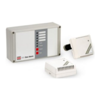
System Overview
The COMBI is a 16 direct (4-20mA) plus 64 addressable channel gas monitoring system
which displays gas concentration and constantly checks for alarm conditions.
Each channel consists of a remote gas sensor located at the point where gas is to be
measured. The direct sensor types are individually wired back to the COMBI where as the
addressable sensors can be connected to a shared CAN bus network minimizing cable
requirements.
Each channel when connected becomes active and is recognized by the system and a
fault occurs if it becomes disconnected. This allows a system to be activated on an
individual sensor basis as commissioning takes place.
The gas types and alarm levels for Direct channels are set at the Combi panel but
addressable types transmit this information to the panel. However, alarm levels for
addressable sensors can be altered at the Combi panel or at the sensor itself.
Alarms can be individually set to be latched (requires reset button to clear) or unlatched
(self clearing).
The panel can be powered from mains or 24V dc input with battery backup terminals.
An output 24V 250mA terminal is available to power user devices.The battery input and
mains voltage is monitored and will create a fault if the voltage is too low but the user has
the option to disable these faults.
The Combi panel controls most actions and its dimmable backlit LCD display is capable
of indicating the state of gas measurements or fault conditions. Likewise, dimmable LED’s
internal and external give additional status information.
Many parameters including a text description of the location of a sensor are
programmable via user and engineer’s menus and retained when power is off. These
parameters are reloaded at the next power up so that the system will perform as it did
previously. The Combi panel also has two RS485 Modbus channels and can send data
when requested to do so to a Modbus master controller thus allowing independent system
management facilities.
Engineering menus allow for diagnostic monitoring of the Modbus transmit and receive
buffers. A remote repeater can also be connected which allows the LCD, LED’s and
buttons to be located elsewhere on a CAN bus as well as remaining functional on the
main panel. A network controller can also be connected which appears as a repeater but
to multiple panels connected to the CAN bus. A real time clock keeps track of time and
this time value is displayed on the LCD and appended to any panel events such as
alarms or faults etc. These events are retained in a 99 event memory which can be
viewed on the LCD or sent to a PC via the RS232 channel. Likewise this RS232 channel
can accept setup parameters from a PC and if needed can send the Combi parameters to
the PC as a simple text file which can be edited. Text is sent out via the RS232 channel
as an additional data logging facility. Events and gas level changes are the main types of
data presented which the user can capture using HyperTerminal (or similar) on a PC.
The current time is transmitted via the CAN bus and any addressable sensor will receive
it. Those addressable sensors with a local LCD display will show this time in addition to
the gas concentration data etc.
- If multiple panels are connected on CAN bus, then the panel with the lowest address
will send the time to the other panels.
2