48
TECHNOLOGIES LTD
Combi 8 Channel
4~20mA Output Module
Set up procedure: 253DIC Issue D
Data Sheet
ref C1147 Issue C
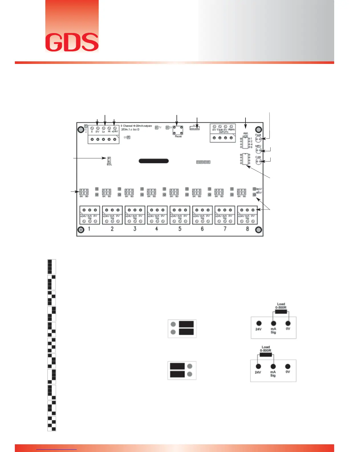
The eight channel 4~20mA output PCB allows signals in either sink or source mode to synchronised
with the Combi 64 addressable and 16 direct sensors. By address selection on “S2”, the eight outputs
can be selected for combinations of Combi sensors as detailed below.
The Combi detects the address being used on this card when connected to the CAN-bus.
According to the address, the outputs represent the following:
“Sink / Source”
(described below)
“End of Line”
Jumper
CAN.Bus to Combi
Processor Reset RS232 PC
Connection
Address Select
(Described below)
Fault LED (activates
if there is no
communication to the
panel)
MPU LED
(Pulses at 1Hz to show
processor is still operating)
CAN LED
(Pulses when data is being
transmitted to Control unit)
Redundant Switch
(option to be introduced in
the future)
Test Pins – to measure
current output
(Note: Load must be
connected)
= Address: 230 = Direct sensors 1 – 8
= Address: 231 = Direct sensors 9 – 16
= Address: 232 = CAN sensors 1 – 8
= Address: 233 = CAN sensors 9 – 16
= Address: 234 = CAN sensors 17 – 24
= Address: 235 = CAN sensors 25 – 32
= Address: 236 = CAN sensors 33 – 40
= Address: 237 = CAN sensors 41 – 48
= Address: 238 = CAN sensors 49 – 56
= Address: 239 = CAN sensors 57 – 64
= Address: 240 = Highest in group 1 – 8
24V0V
Jumper configurations for Sink / Source mode:
= 4~20mA Source
= 4~20mA Sink