39
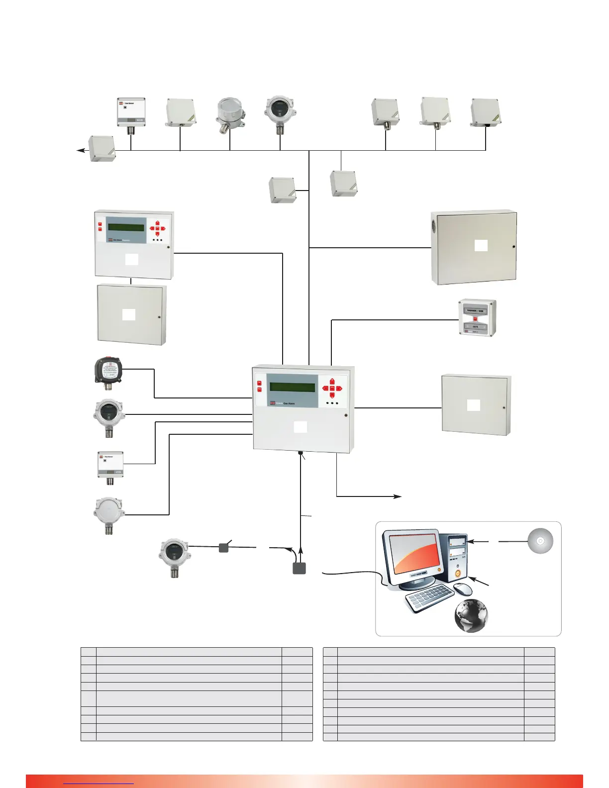
Fig. 2 System Configuration
1~64 CAN Addressable Sensors
Repeater Panel
x16 max
4 core - 1km max
3 or 2 core
1~16
Direct Sensors
(4~20mA source)
3 core
2 core
4 core
CAN 4 way
Alarm Relay unit
x16 max
CAN 1
Repeater
CAN 2 only
24vDC
Power Pack
21+ sensors
Status
Indicator
x unlimited
32 Way Relay Unit
x2 max
Dual Coms - Modbus 485
Data storage
USB high speed
serial adaptor
(if required by PC)
Stand-alone
Sensor
Ribbon Cable
10 way
2m max
Combi
9-D type
9-D type
Ref Description Part No
A Combi Control Unit - 64 + 16 Sensors 160-100
B Combi Repeater Panel 160-200
C Combi 64 Way Data Logger Software 160-500
D Combi Additional Relay Panel - 32 Way 007-613
E Status Indicator II 007-011
F Combi Auxiliary Power Pack 11A @ 24vDC
(required for use with 21 or more sensors) 200-003
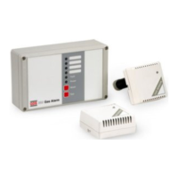
G 20JF1 Flam / Toxic Gas Sensor SAFE AREA (Display)
H 40JF6 Flam / Toxic Gas Sensor SAFE AREA
I XDIF1 Flam / Toxic Gas Sensor HAZARDOUS AREA
J XDIWIN F1 Flam / Toxic Gas Sensor HAZARDOUS AREA
Ref Description Part No
K 20JF1 Flam / Toxic Gas Sensor SAFE AREA
L 40JF1 Flam / Toxic Gas Sensor SAFE AREA
M 40JP1 Toxic Gas Sensor SAFE AREA
N 9000JF1 Flam / Toxic Gas Sensor HAZARDOUS AREA
O RS232 Interface Adapter Lead 160-515
P RS232 to USB Adapter Lead + Software 160-520
Q RS232 Interface Adapter Unit 160-510
R CAN Alarm Relay Module in 20JJB - 4 Relay 160-205
S 8 way 4~20mA output signals
T Sensor Booster Unit
P
C
D
E
O
Q
A
N
B
R
F
G
H
I
J
K L
M
Sensor programming
Combi Soft
Data logging/storage
System monitoring
Combi Panel
programming
via text file
T
Sensor Signal
Booster up to 1km
S
8 way 4~20mA
output unit
D
Worldwide
internet access