44
ISO 9001
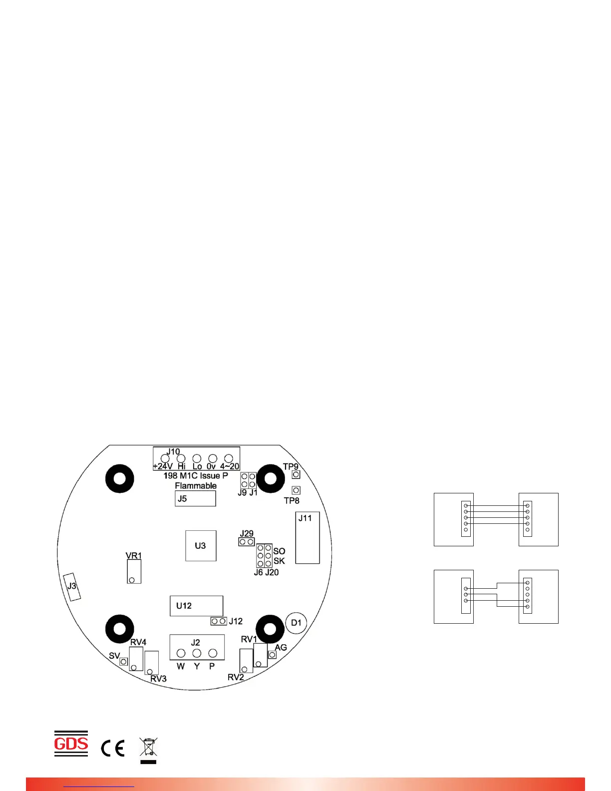
Fig. 1
Using magnets (set up)
The Combi sensors which have an LCD display fitted also incorporate 3 reed switches which can be activated using
external magnets through the glass window of the flameproof XDIwin enclosure. These magnets do not act instantly and
have to be in close proximity to L, M and R on the front display for a few seconds to activate a software setup function.
The left magnet enters the auto zero ON or OFF menu. This allows small drift changes in the sensor to be compensated
for but is not operational when the sensor readings are greater than 5% of full scale. Therefore auto zero is inactive when
a larger gas reading is present. When the remove magnets message appears, move the left magnet away and then the
display shows if auto zero is ON or OFF. The left magnet puts auto zero ON and the right magnet turns it OFF. With no
magnets present, the display will return to normal and after a few seconds timeout.
The right magnet allows the CAN address of the sensor to be changed. When the address menu is displayed with a
prompt to remove the magnet, and then the display shows the address and that the right magnet will decreases it whilst
the left magnet will increase it. This is then stored in internal non-volatile memory and the display will automatically revert
to normal operation.
The centre magnet is used to inhibit the sensor. As with the left and right magnet functions the display requests that you
remove the magnet and then the state of inhibit appears on the LCD. the left magnet then puts the sensor into inhibit whilst
the right magnet removes it. The amber LED on the front panel under the LCD flashes when the sensor is inhibited. When
all magnets are removed, the display will revert to normal operation. The direction of the alarms is displayed as ^ for rising
and v for falling but these can be changed using left and right magnets together.
The left and right magnets together allow the calibration menu to be used.
Removing both magnets as instructed on the LCD presents the first part of this multi menu which is ZERO. With no gas
present use the left magnet to increase the reading and the right magnet to decrease to achieve a zero reading on the
displayed gas. A timer is displayed on the LCD and when this reaches 0, the next menu is displayed. This timer is 15
seconds approximately and is reset back each time a magnet is near. Waiting till timeout is acceptable but this timeout can
be speeded up by placing a magnet near to the centre position.
SPAN is the next part of the menu and gas should be applied to the sensor at this time. The left magnet now increases
the gain and the right magnet reduces gain. The actual sensor value can be seen on the display to rise or fall respectively.
LOW ALARM is the next menu and left and right magnets increase and decrease this value.
HIGH ALARM is next followed by OVER RANGE alarm.
The direction of the alarms is displayed as ^ for rising and v for falling but these can be changed using left and right
magnets together.