Model 94x/97x Proximity Reader
Installation Manual
28
Connecting the reader
For pinout and wiring information, refer to the following:
• Pinouts on page 28
• Wiring diagrams on page 29
Note: To maintain CE compliance, shielded cable and connections must
be used as shown in the section, “CE/FCC compliance” on page 46.
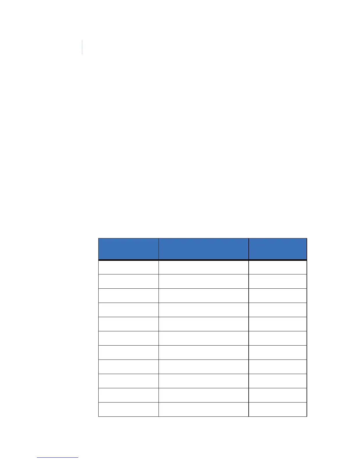
Pinouts
The table below shows the pinouts for connecting the reader to
the microcontroller. Connector J1, pin 1 is to the right as you
view the connector from behind the reader. See Figure 10 on
page 22 and Figure 11 on page 23.
Table 6. Pinouts
Connector: J1
Pin number
Signal Pigtail Wire Color
1+12 VDC Red
2 Ground Black
3 Red LED External Drive Blue
4 Green LED External Drive Brown
5 Yellow LED External Drive Orange
6 Reader Data 0 Green
7 Reader Data 1 White
8 Beeper External Drive Violet
9Keying Pin
10 Door DI (Door Contact Switch) Yellow
11 Exit DI (Exit Request Button) Gray