COE Communications Engineering Document
Author:
Keith Gilbertson
Rev:
A
Date:
3/08/02
Pag
e:
20
of
33
GE
TRANSPORTATION
SYSTEMS
GLOBAL SIGNALING DIVISION
Title:
12RII FCC TECHNICAL MANUAL
7. Kenwood RFPA & TXRX Modules
The Radio Control Board interfaces the TXRX modules on J11 flex circuit connector. All controls to the RF modules are
through this connection. See the Appendix on Kenwood modules for descriptions and block diagrams.
8. POWER SUPPLY BOARD
8.1. General Description
The 12RII Power Supply Board (PSB) provides the regulated voltages necessary from the host battery input voltage of 74VDC
found on most locomotives, or 37VDC found on typical transit cars. The primary battery inputs voltages are isolated from the
radio chassis and internal voltages by the DC/DC converter module.
The primary battery input as well as the secondary 13V input is protected against reverse polarity. The DC/DC converter is
protected with Transient Voltage Suppression (TVS), filtering, and Over Voltage Protection (OVP) circuits to avoid damage of
the converter or the internal radio circuitry.
The PSB provides regulated 13VDC, 8VDC and 5VDC signals to power the internal radio modules.
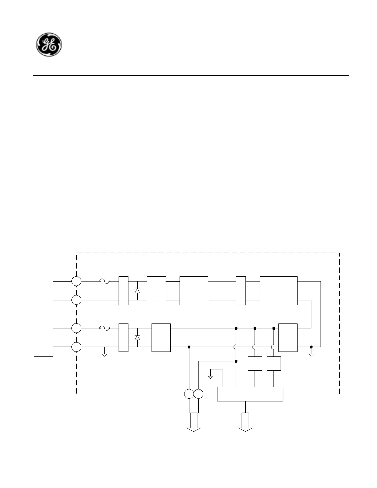
8.2. Block Diagram
J1
J2
LC
FILTER
T
V
S
COMMON
MODE
FILTER
J3
J4
T
V
S
J6 J5
CAP
FILTER
LC
FILTER
PS1
DC/DC
CONVERTER
POWER SUPPLY
W2
BLK
W1
RED
+
-
+Vin
-Vin
+13.6V
-13.6V
W3
B+
COM
+V
-V
BLK
RED
ORN
BLU
F1
F2
COM B+ 8V 5V
J7
U2
8V
REG
U3
5V
REG
O
V
P
A
C
D
B
J4
TO
RFPA
TO
RCB

 Loading...