COE Communications Engineering Document
Author:
Keith Gilbertson
Rev:
A
Date:
3/08/02
Pag
e:
8
of
33
GE
TRANSPORTATION
SYSTEMS
GLOBAL SIGNALING DIVISION
Title:
12RII FCC TECHNICAL MANUAL
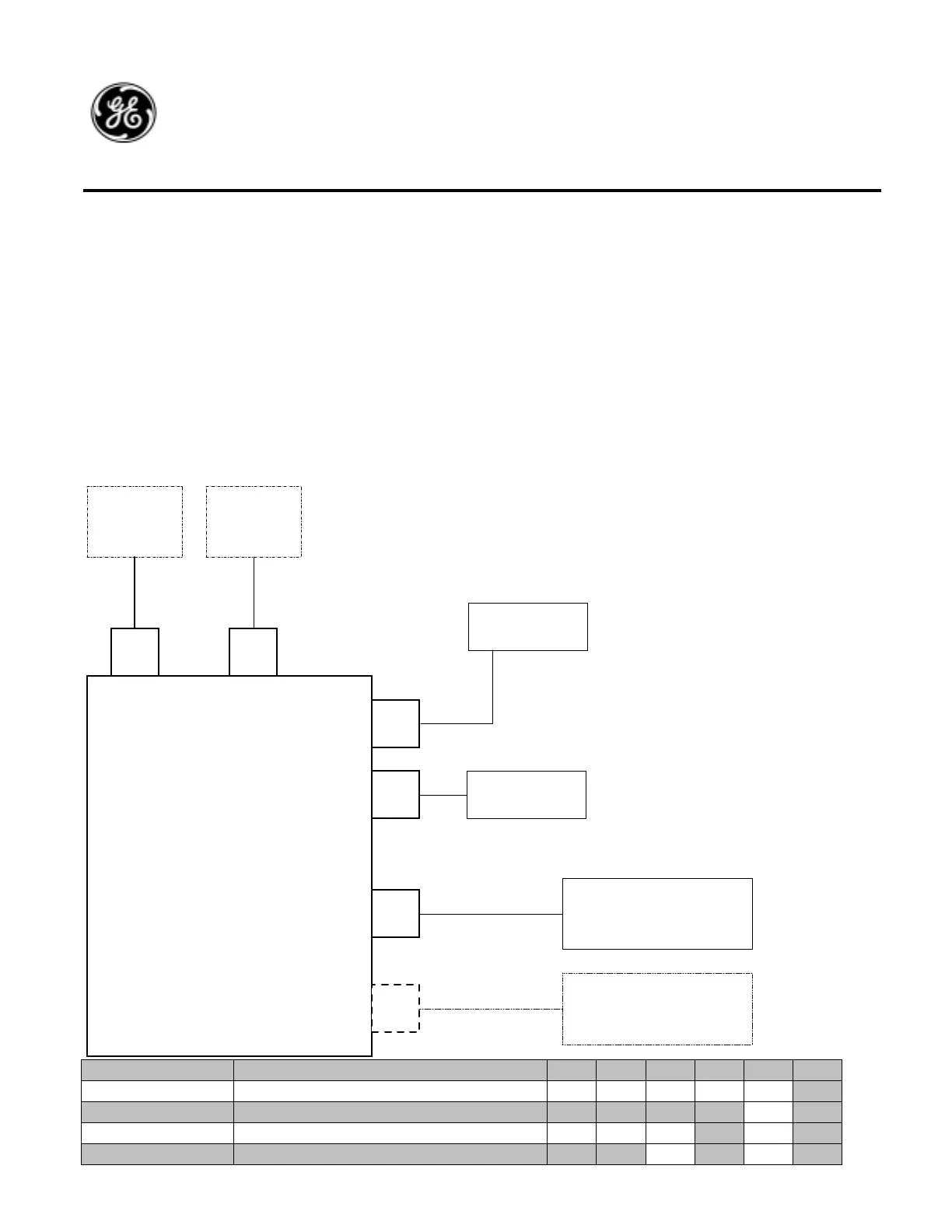
5.3. Serial Remote Radio Systems (Future Option)
5.3.1. General Description
The standard 12RII-SR radio is identical in operation to the 12RII-LC radio except that it is not mounted in the typical brake
stand enclosure. The Serial Remote Control Head that is used in conjunction with the 12RII-SR radio is mounted in the control
stand location. The radio is mounted in a locker or in the nose of the engine. A Serial Interface Cable is used to connect the
radio to the control head.
Optionally the radio supports the connection of a second control head on J8 and a radio handset at J2. Program connector J3 is
also standard as on the other radio systems.
5.3.2. Block Diagram
5.3.3. Basic
Oper
ation
Operation of
the 12RII-SR
radio is
identical to the
12RII-LC
radio. The
front panel
assembly is
identical in
both radio
systems.
5.4. Radi
o
Fina
l
Asse
mbl
y
Part
s
List
251303-0000 ASSY 12RII-LC 74V VHF X
251303-0001 ASSY 12RII-LC 74V VHF W/J6 X
251303-0100 ASSY 12RII-LC 36V VHF X
251303-0101 ASSY 12RII-LC 36V VHF W/J6 X
251303-1000 ASSY 12RII-RC 74V VHF X
PC Handset
Antenna
Primary
Serial Remote
Control Head
Battery
12RII-SR
Serial Remote Radio
System
J4
J1
J2J3
J7
J8
Optional 2nd
Serial Remote
Control Head

 Loading...