COE Communications Engineering Document
Author:
Keith Gilbertson
Rev:
A
Date:
3/08/02
Pag
e:
15
of
33
GE
TRANSPORTATION
SYSTEMS
GLOBAL SIGNALING DIVISION
Title:
12RII FCC TECHNICAL MANUAL
6.4. Radio Interfaces Signals
This section identifies the Interface signals associated with each connector used in the radio system(s).
6.4.1. External Connector Configurations
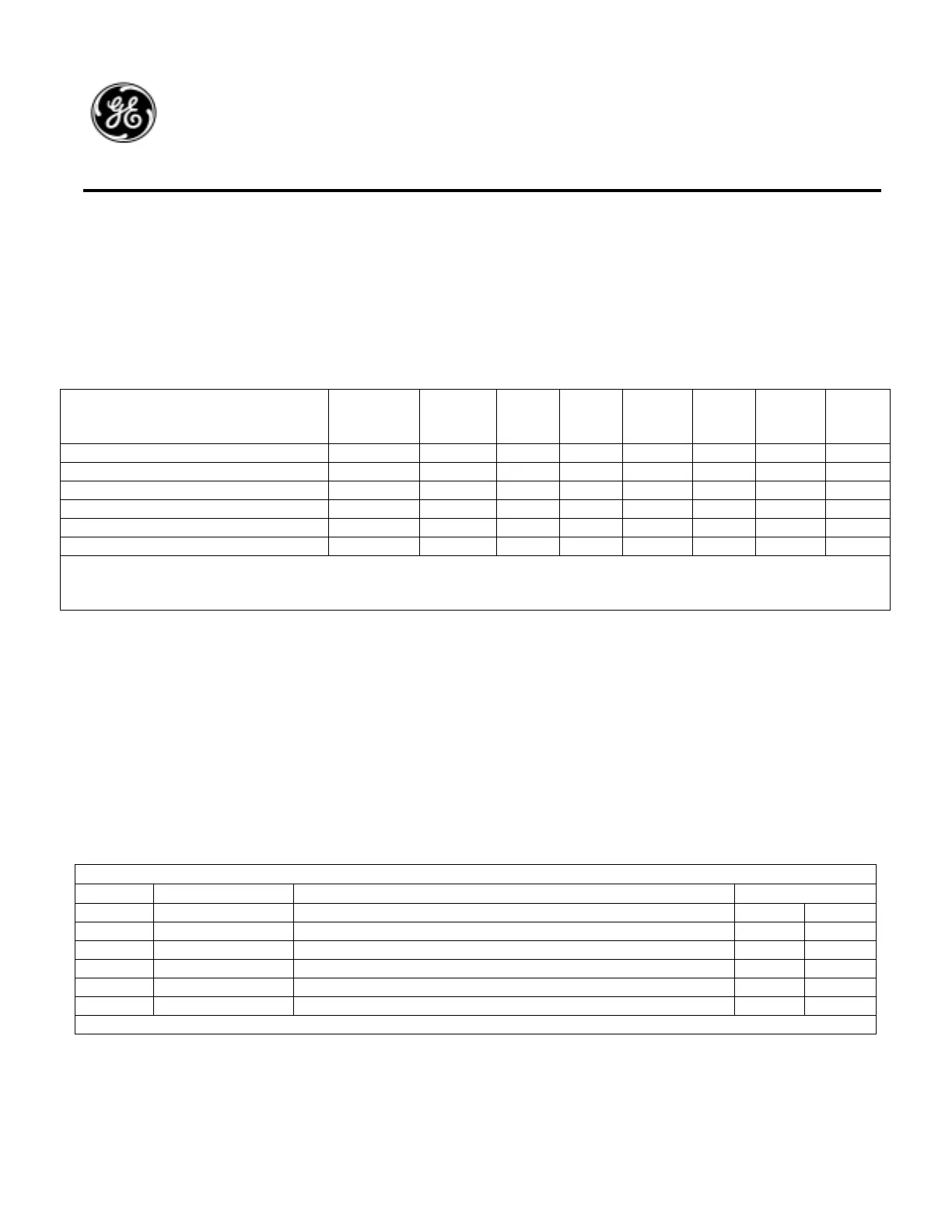
The following table shows the standard radio connectors associated with each of the typical RC, LC & SR radio systems.
Although other connector options are possible, this list covers all possible applications knows to date.
6.4.2. J1 Antenna
J1 is an industry standard UHF (SO-49) connector used to interface to the voice radio antenna. J1 is connects to CN4 on the
RFPA board with a short piece of wire. This connector is common to all radio systems.
6.4.3. J2 6-Pin Handset
J2 supports an interface to a standard AAR 6-pin handset. Connector Pins, Signal Names, and descriptions are shown in the
table below. This connector is standard on all radio systems and interfaces in a common cable with J3 Program connector to J2
on the RCB.
J2 AAR HANDSET SIGNAL INTERFACE
J2-Pin Signal Description Mating Connector
A Mic-Audio Modulation Input from the handset condenser. RCB J2-1
B Mic-Com Microphone Audio return (common with radio chassis). RCB J2-2
C PTT Push-To-Talk radio key input. RCB J2-3
D PTT-Com PTT Return (common with radio chassis). RCB J2-4
E Rec-Audio Audio output to receiver element in handset. RCB *J2-5
F HK Optional “Off Hook signal input. RCB *J2-6
* Either of these signals may be connected to J2-10 if interfacing to a DTMF Palm Mic which requires B+ voltage.
6.4.4. J3 9-Pin Program
J3 provides an interface to a PC used for uploading and downloading firmware, radio statistics or configuration files. This is a
standard 9-pin Mini-D connector. This connector is standard on all radio systems and interfaces in a common cable with J2
Handset connector to J2 on the RCB. J3 interface signals are shown below.
Radio Model Description
J1
Antenna
J2
Handset
J3
PGM
J4
4-Pin
J5
23-Pin
J6 **
12-Pin
J7
Serial 1
J8
Serial
2
RC – AAR Remote X X X X
LC – Clean Cab X X X X
LC – Clean Cab W/Access X X X X X
LC – Clean Cab W/ 2
nd
Control Head X X X X *X
SR – Serial Remote X X X X X
SR – Serial Remote W/2
nd
Control Head X X X X X X
* J8 may be physically mounted on radio in the location typically used by J6. This is to allow for connection to existing cables
which may be to short to reach J8 location on the chassis.
** In some applications J6 is a 15 pin connector.

 Loading...