COE Communications Engineering Document
Author:
Keith Gilbertson
Rev:
A
Date:
3/08/02
Pag
e:
16
of
33
GE
TRANSPORTATION
SYSTEMS
GLOBAL SIGNALING DIVISION
Title:
12RII FCC TECHNICAL MANUAL
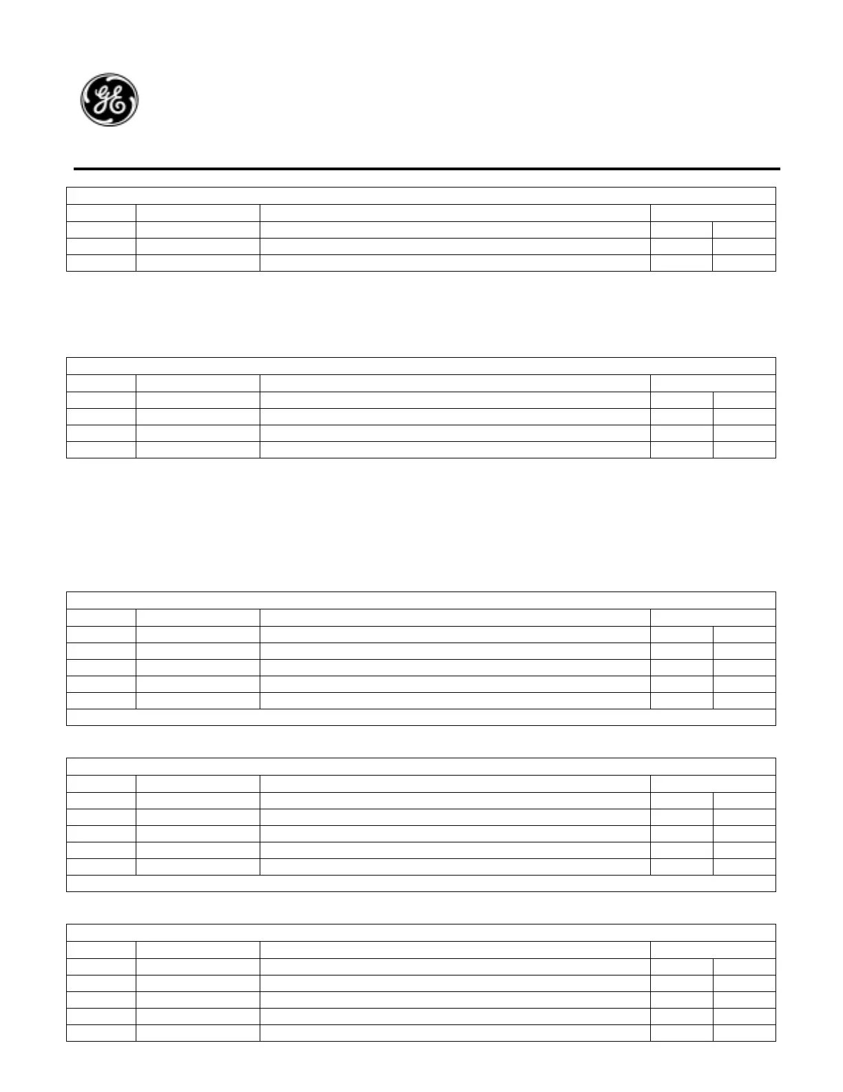
J3 PROGRAM SIGNAL INTERFACE
J3-Pin Signal Description Mating Connector
2 Rx Data RS-2323 Serial Receive Data Input RCB J2-7
3 TX Data RS-2323 Serial Transmit Data Output RCB J2-8
5 Com Signal Common (common to radio chassis). RCB J2-9
6.4.5. J4 4-Pin Power Connector
J4 is used for primary and secondary input voltages for the 12RII-LC and 12RII-SR radio systems. The J4 cable plugs into J1-
J4 on the Power Supply Board. J4 typical signal interfaces are shown in the table below.
J4 4-PIN POWER SIGNAL INTERFACE
J4-Pin Signal Description Mating Connector
A +74VDC Primary isolated input voltage PSB J1 / J2
B 13 VDC Com Common (radio chassis). PSB J4
C -74VDC Primary isolated input voltage return. PSB J2 / J1
D +13 VDC Secondary (Test) radio input voltage. PSB J3
6.4.6. J5 23-Pin Power & Control
J5 is used for input power, control and audio signal interfaces on the 12RII-RC radio. The J5 cable assembly plugs into J1-J4
on the Power Supply Board and J5 & J6 on the Radio Control Board.
The Following tables are the currently defined power interfaces used on 74V, 37V and 13V AAR Remote Control Radio
systems.
Standard 74 & 37 Volt Power Input.
J5 23-PIN POWER SIGNAL INTERFACE (STD)
J5-Pin Signal Description Mating Connector
1- --
2 * +VIN Isolated input voltage PSB J1
3 * -VIN Isolated input voltage return PSB J2
4 +13VDC 13V Output PSB J3
5 13V COM 13V Common (radio chassis) PSB J4
* Radio must be specified as either 74V or 37V.
Alternate 37V Power Input.
J5 23-PIN POWER SIGNAL INTERFACE (37V ALT.)
J5-Pin Signal Description Mating Connector
1- --
2 --
3 * -VIN Isolated input voltage return PSB J2
4 * +VIN Isolated input voltage PSB J1
5 13V COM 13V Common (radio chassis) PSB J4
* These are for an alternate 37V Battery Interface.
13V Power Input.
J5 23-PIN POWER SIGNAL INTERFACE (13V Only)
J5-Pin Signal Description Mating Connector
1 13V RTN Non-Isolated input voltage return PSB J1
2 +13V Non-Isolated Input voltage PSB J2
3- --
4 +13VDC 13V Output PSB J3
5 13V COM 13V Common (radio chassis) PSB J4
 Loading...
