COE Communications Engineering Document
Author:
Keith Gilbertson
Rev:
A
Date:
3/08/02
Pag
e:
17
of
33
GE
TRANSPORTATION
SYSTEMS
GLOBAL SIGNALING DIVISION
Title:
12RII FCC TECHNICAL MANUAL
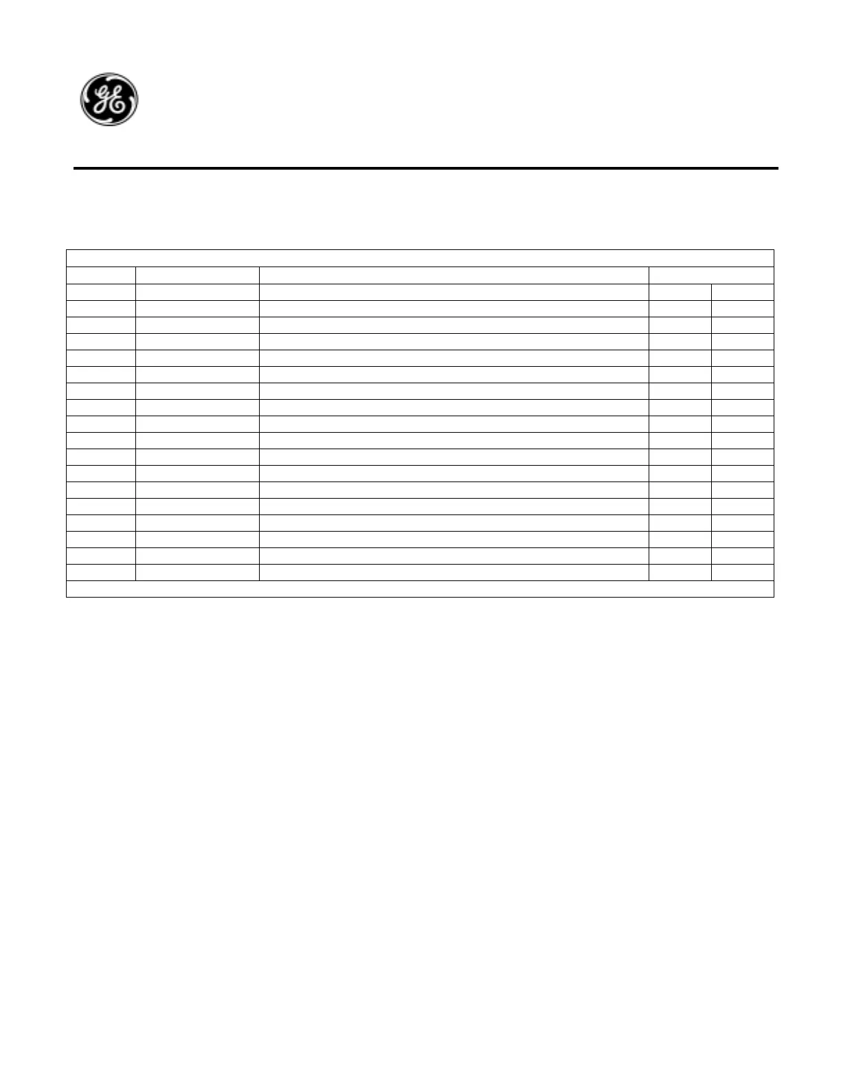
The following table illustrates the standard control and audio signals.
J5 23-PIN CONTROL & AUDIO SIGNAL INTERFACE
J5-Pin Signal Description Mating Connector
6 Mic-Com Remote Microphone audio return RCB J6-2
7 Mic-Audio Remote Microphone audio input RCB J6-1
8 8 Ohm Audio Out 10W 8 ohm audio speaker output RCB J5-3
9 PTT Remote PTT input RCB J6-3
10 CH1 AAR Channel 1 Input Select Line RCB J5-4
11 CH2 AAR Channel 2 Input Select Line RCB J5-5
12 CH3 AAR Channel 3 Input Select Line RCB J5-6
13 CH4 AAR Channel 4 Input Select Line RCB J5-7
14 * TX Ind. I/O 1- transmit indication output RCB J6-9
15 Rec-Audio Remote low level receive audio output RCB J6-5
16 Audio Return Audio Common (radio chassis) RCB J6-7
17 * Standby I/O 2 - Standby indication output RCB J6-10
18 Channel Return AAR Channel Return Input RCB J5-8
19 N.C. --
20 13V Com Common (radio chassis) RCB J6-8
21 +13V Out Low Power 13V Output, fuse protected RCB J6-6
22 * QL Disable I/O 3 - QL disable input RCB J5-1
23 *Mute I/O 4 - Speaker Mute RCB J5-2
* I/O signals are programmable for user configurations. Signal functions are shown for reference only.
 Loading...
