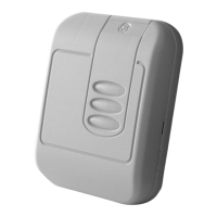
GE Contactless Smart Card Reader Model 24x 9
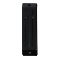
When installing two readers back-to-back on a wall that will separate
the two readers by four inches (101.60 mm) or less, a metal plate (for
example: Reader isolation plate, metal wall) must be placed between
the readers. To obtain the maximum read range, mount each GE
Model 24x Smart Card Reader onto one or more Isolation Spacers.
Note: Two readers can simultaneously read the same badge or tag if the
distance between the two readers is less than four inches (101.60 mm),
back-to-back.
Micro Compatibility
• Micro/5 Controller with either 2RP or 8RP Reader Boards: refer to
the Micro/5 Installation Guide.
IMPORTANT: DO NOT use the GE Model 24x Readers with the Micro/5 2SRP.
• Micro/PX-2000 and Micro/PXN-2000 controllers: refer to the Micro/
PX-2000 and Micro/PXN-2000 Installation Guide.
• Micro/Reader-Junction Box: refer to the point-to-point wiring
diagrams in this manual.
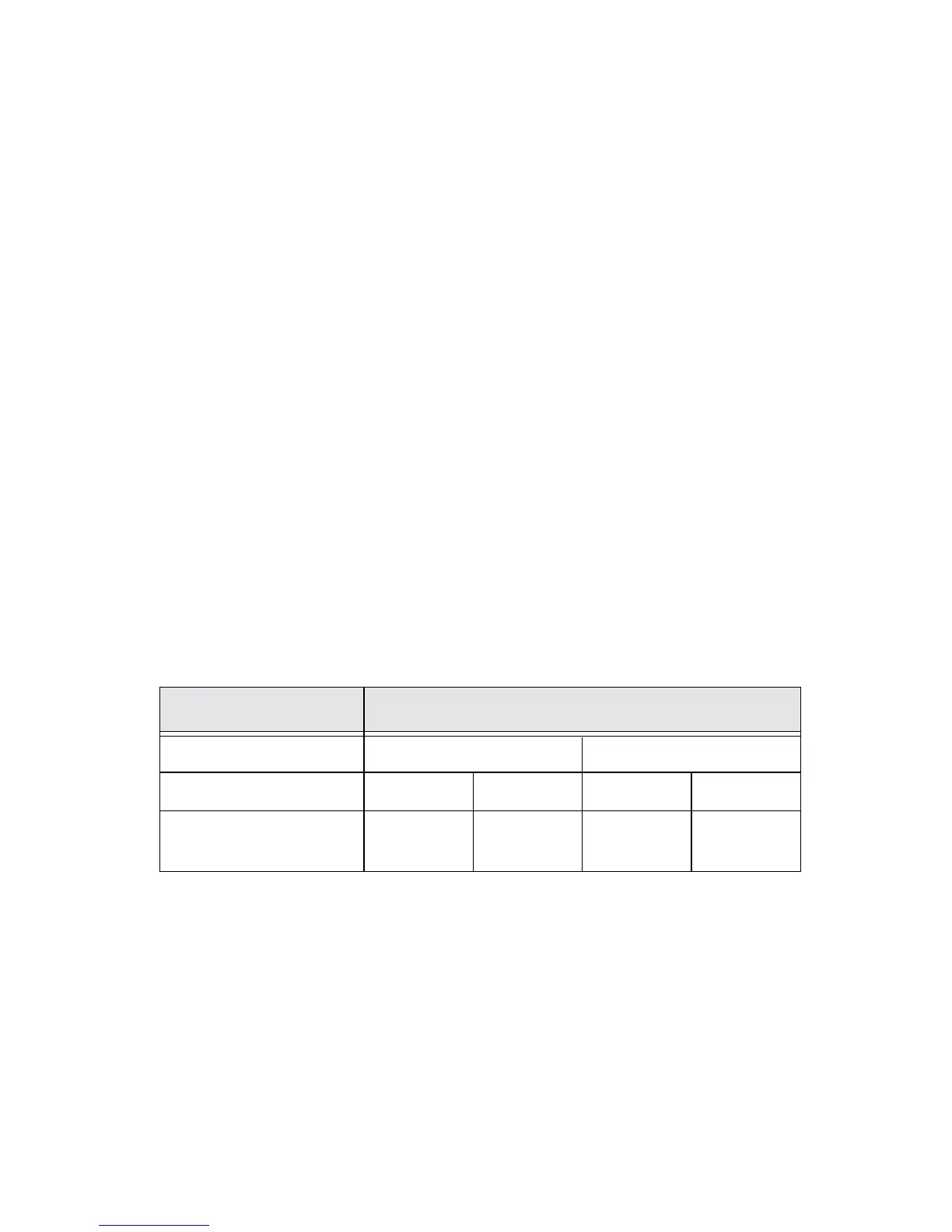
Reader-to-Micro Wiring Distance
Table 1: Current and Cable Distance
Keypad Operation: Model 245
The reader sends each key press to the microcontroller and the yellow
LED will blink. The reader beeper sounds with each key press.
Supply Voltage Cable Distance
Model 240 and 245 12 VDC 13.6 VDC
Current 18 AWG 22 AWG 18 AWG 22 AWG
105 mA @12 VDC 2,041 ft.
(622 m)
856 ft.
(262 m)
3,123 ft.
(952 m)
1,309 ft.
(399 m)