GE Power Management 750/760 Feeder Management Relay 16-
73
16 COMMUNICATIONS 16.4 MODBUS MEMORY MAP
16
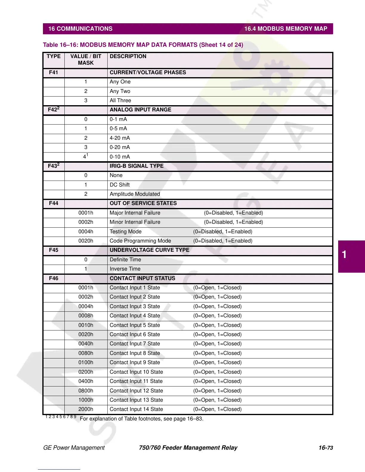
F41 CURRENT/VOLTAGE PHASES
1 Any One
2Any Two
3All Three
F42
2
ANALOG INPUT RANGE
00-1 mA
10-5 mA
24-20 mA
30-20 mA
4
1
0-10 mA
F43
2
IRIG-B SIGNAL TYPE
0 None
1 DC Shift
2 Amplitude Modulated
F44 OUT OF SERVICE STATES
0001h Major Internal Failure (0=Disabled, 1=Enabled)
0002h Minor Internal Failure (0=Disabled, 1=Enabled)
0004h Testing Mode (0=Disabled, 1=Enabled)
0020h Code Programming Mode (0=Disabled, 1=Enabled)
F45 UNDERVOLTAGE CURVE TYPE
0 Definite Time
1 Inverse Time
F46 CONTACT INPUT STATUS
0001h Contact Input 1 State (0=Open, 1=Closed)
0002h Contact Input 2 State (0=Open, 1=Closed)
0004h Contact Input 3 State (0=Open, 1=Closed)
0008h Contact Input 4 State (0=Open, 1=Closed)
0010h Contact Input 5 State (0=Open, 1=Closed)
0020h Contact Input 6 State (0=Open, 1=Closed)
0040h Contact Input 7 State (0=Open, 1=Closed)
0080h Contact Input 8 State (0=Open, 1=Closed)
0100h Contact Input 9 State (0=Open, 1=Closed)
0200h Contact Input 10 State (0=Open, 1=Closed)
0400h Contact Input 11 State (0=Open, 1=Closed)
0800h Contact Input 12 State (0=Open, 1=Closed)
1000h Contact Input 13 State (0=Open, 1=Closed)
2000h Contact Input 14 State (0=Open, 1=Closed)
Table 16–16: MODBUS MEMORY MAP DATA FORMATS (Sheet 14 of 24)
TYPE VALUE / BIT
MASK
DESCRIPTION
1 2 3 4 5 6 7 8 9
For explanation of Table footnotes, see page 16–83.