16-
74
750/760 Feeder Management Relay GE Power Management
16.4 MODBUS MEMORY MAP 16 COMMUNICATIONS
16
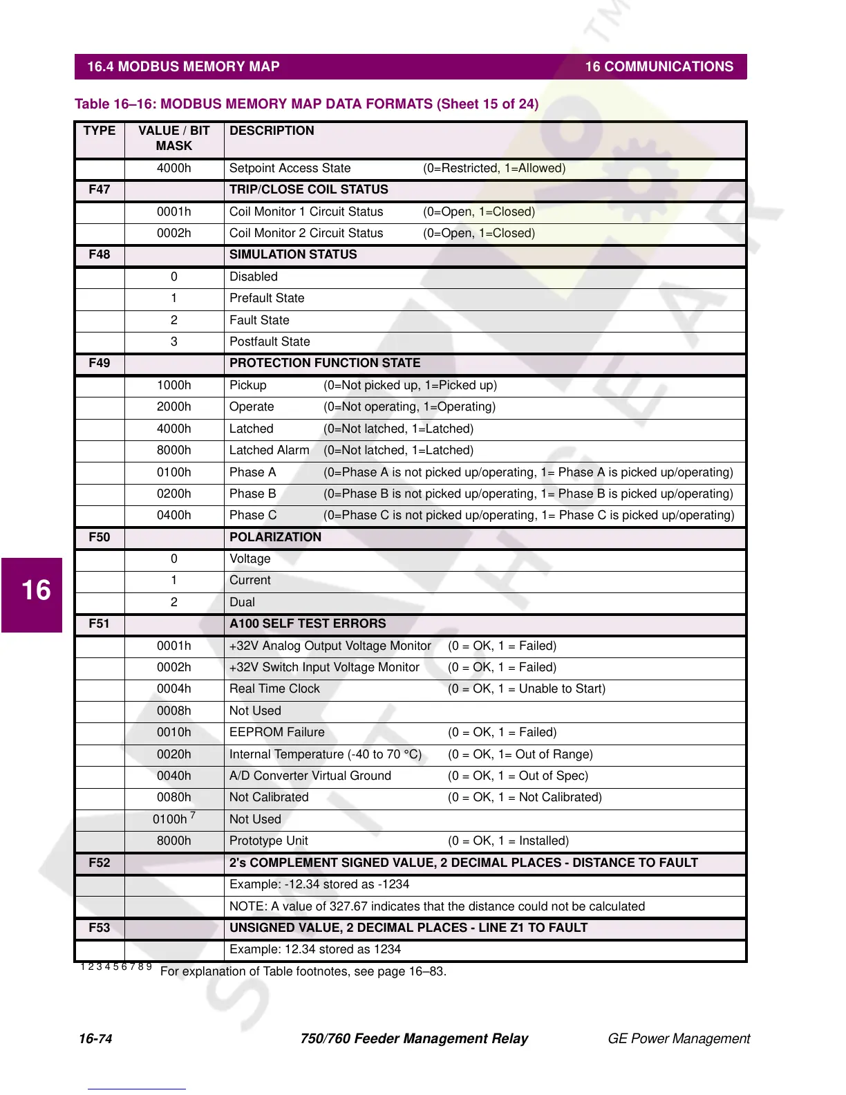
4000h Setpoint Access State (0=Restricted, 1=Allowed)
F47 TRIP/CLOSE COIL STATUS
0001h Coil Monitor 1 Circuit Status (0=Open, 1=Closed)
0002h Coil Monitor 2 Circuit Status (0=Open, 1=Closed)
F48 SIMULATION STATUS
0 Disabled
1 Prefault State
2 Fault State
3 Postfault State
F49 PROTECTION FUNCTION STATE
1000h Pickup (0=Not picked up, 1=Picked up)
2000h Operate (0=Not operating, 1=Operating)
4000h Latched (0=Not latched, 1=Latched)
8000h Latched Alarm (0=Not latched, 1=Latched)
0100h Phase A (0=Phase A is not picked up/operating, 1= Phase A is picked up/operating)
0200h Phase B (0=Phase B is not picked up/operating, 1= Phase B is picked up/operating)
0400h Phase C (0=Phase C is not picked up/operating, 1= Phase C is picked up/operating)
F50 POLARIZATION
0Voltage
1 Current
2 Dual
F51 A100 SELF TEST ERRORS
0001h +32V Analog Output Voltage Monitor (0 = OK, 1 = Failed)
0002h +32V Switch Input Voltage Monitor (0 = OK, 1 = Failed)
0004h Real Time Clock (0 = OK, 1 = Unable to Start)
0008h Not Used
0010h EEPROM Failure (0 = OK, 1 = Failed)
0020h Internal Temperature (-40 to 70 °C) (0 = OK, 1= Out of Range)
0040h A/D Converter Virtual Ground (0 = OK, 1 = Out of Spec)
0080h Not Calibrated (0 = OK, 1 = Not Calibrated)
0100h
7
Not Used
8000h Prototype Unit (0 = OK, 1 = Installed)
F52 2's COMPLEMENT SIGNED VALUE, 2 DECIMAL PLACES - DISTANCE TO FAULT
Example: -12.34 stored as -1234
NOTE: A value of 327.67 indicates that the distance could not be calculated
F53 UNSIGNED VALUE, 2 DECIMAL PLACES - LINE Z1 TO FAULT
Example: 12.34 stored as 1234
Table 16–16: MODBUS MEMORY MAP DATA FORMATS (Sheet 15 of 24)
TYPE VALUE / BIT
MASK
DESCRIPTION
1 2 3 4 5 6 7 8 9
For explanation of Table footnotes, see page 16–83.