16-
76
750/760 Feeder Management Relay GE Power Management
16.4 MODBUS MEMORY MAP 16 COMMUNICATIONS
16
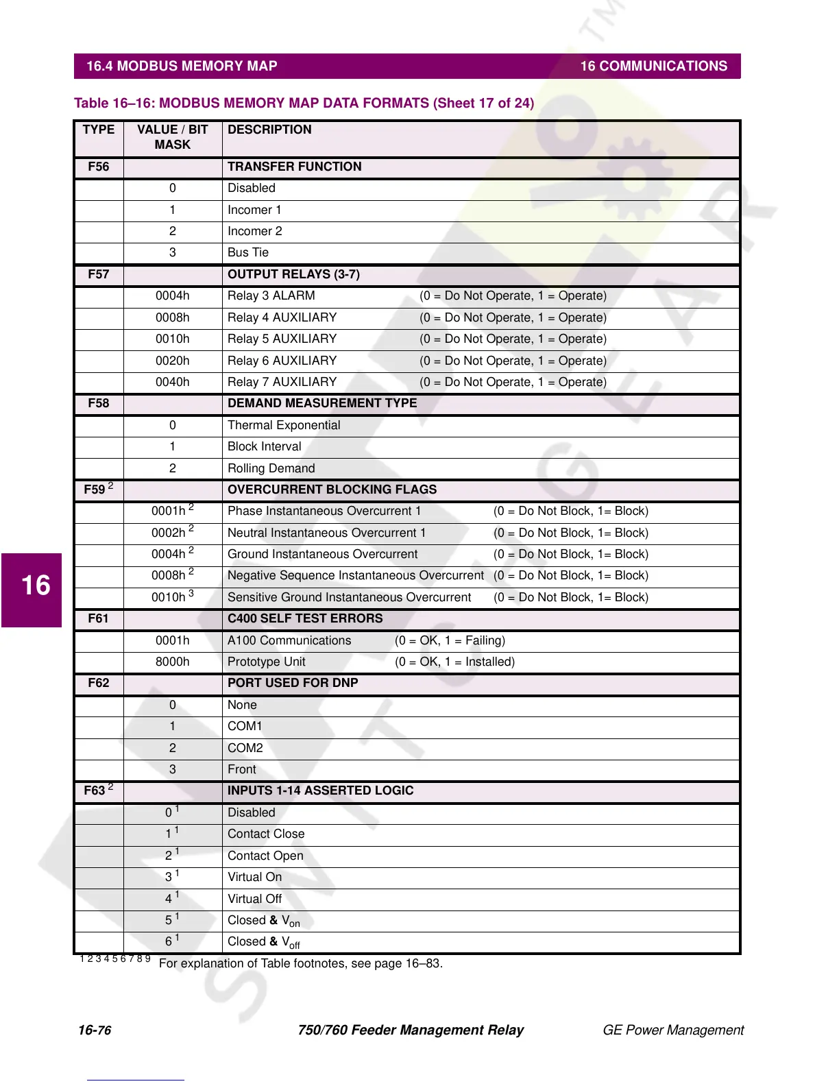
F56 TRANSFER FUNCTION
0 Disabled
1 Incomer 1
2 Incomer 2
3Bus Tie
F57 OUTPUT RELAYS (3-7)
0004h Relay 3 ALARM (0 = Do Not Operate, 1 = Operate)
0008h Relay 4 AUXILIARY (0 = Do Not Operate, 1 = Operate)
0010h Relay 5 AUXILIARY (0 = Do Not Operate, 1 = Operate)
0020h Relay 6 AUXILIARY (0 = Do Not Operate, 1 = Operate)
0040h Relay 7 AUXILIARY (0 = Do Not Operate, 1 = Operate)
F58 DEMAND MEASUREMENT TYPE
0 Thermal Exponential
1 Block Interval
2 Rolling Demand
F59
2
OVERCURRENT BLOCKING FLAGS
0001h
2
Phase Instantaneous Overcurrent 1 (0 = Do Not Block, 1= Block)
0002h
2
Neutral Instantaneous Overcurrent 1 (0 = Do Not Block, 1= Block)
0004h
2
Ground Instantaneous Overcurrent (0 = Do Not Block, 1= Block)
0008h
2
Negative Sequence Instantaneous Overcurrent (0 = Do Not Block, 1= Block)
0010h
3
Sensitive Ground Instantaneous Overcurrent (0 = Do Not Block, 1= Block)
F61 C400 SELF TEST ERRORS
0001h A100 Communications (0 = OK, 1 = Failing)
8000h Prototype Unit (0 = OK, 1 = Installed)
F62 PORT USED FOR DNP
0 None
1COM1
2COM2
3Front
F63
2
INPUTS 1-14 ASSERTED LOGIC
0
1
Disabled
1
1
Contact Close
2
1
Contact Open
3
1
Virtual On
4
1
Virtual Off
5
1
Closed
&
V
on
6
1
Closed
&
V
off
Table 16–16: MODBUS MEMORY MAP DATA FORMATS (Sheet 17 of 24)
TYPE VALUE / BIT
MASK
DESCRIPTION
1 2 3 4 5 6 7 8 9
For explanation of Table footnotes, see page 16–83.