15
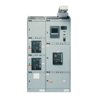
Operations Counter –
Field installable kit available (Breaker accessory)
T
he operations counter mounts on the breaker as a five-
digit, non-resettable counter actuated by the breaker
c
losing mechanism.
Table 15.1 Field Installable Operations Counter Kit catalog number
“PM-Ready” – (Breaker accessory)
In its most basic form, a manually operated WavePro breaker,
with a Power+
™
or MicroVersaTrip Plus
™
trip unit and no
other accessories, may be able to be supplied without sec-
ondary disconnect points. The “PM-Ready” option equips the
breaker with a secondary disconnect and inputs for 24Vdc
auxiliary power, communications and 3-phase voltage signals.
If the breaker is already equipped with any combination of
ground fault protection, zone selective interlocking, shunt
trip, auxiliary switch, bell alarm, undervoltage device, electric
lockout, MicroVersaTrip PM
™
or is electrically operated, the
PM-ready wiring is automatically included and does not have
to be specified. This “PM-Ready” option makes upgrading a
WavePro breaker to MicroVersaTrip PM as simple as changing
the trip unit.
Position Switch – By-pass switch or TOC truck-operated-
contact (Equipment accessory)
This accessory is available with either two NO and two NC or
six NO and six NC electrically separate contacts. The switch
changes state when the breaker is racked from the CONNECT
to the TEST position. The position switch is used to indicate
the drawout position of the breaker, enable/disable control
cir
cuits, and/or bypass auxiliar
y contacts when the br
eaker
is in the TEST/DISCONNECT/WITHDRAWN positions.
T
able 15.2
P
osition switch ratings
Racking Tool – (Equipment accessory)
The rack
ing tool is a special driv
e wr
ench with a squar
e
1
⁄2"
socket that engages the racking mechanism on the breaker.
One rack
ing tool is used for all W
avePro
™
cir
cuit br
eakers.
0324B4721G001
Without universal joint – all applications except as noted
below (standar
d)
0324B4724G001
With universal joint – must use for outdoor applications
when ther
e is a lar
ge frame (3200 – 5000A) br
eak
er or fuse
r
ollout on the extr
eme right end of the line-up
. Can be used
on all other breaker applications, also.
Remote Charge Indicator Switch –
Field installable kit available (Breaker accessory)
The remote charge indicator switch is a normally open or
normally closed dry contact that changes state when the
c
losing springs of the breaker are fully charged. This option is
available on manually or electrically operated breakers. The
c
ontact is rated 4.0 amps at 120Vac and 0.5 amps at 125Vdc.
Table 15.3 Field Installable Remote Charge Indicator Switch Kit
catalog numbers
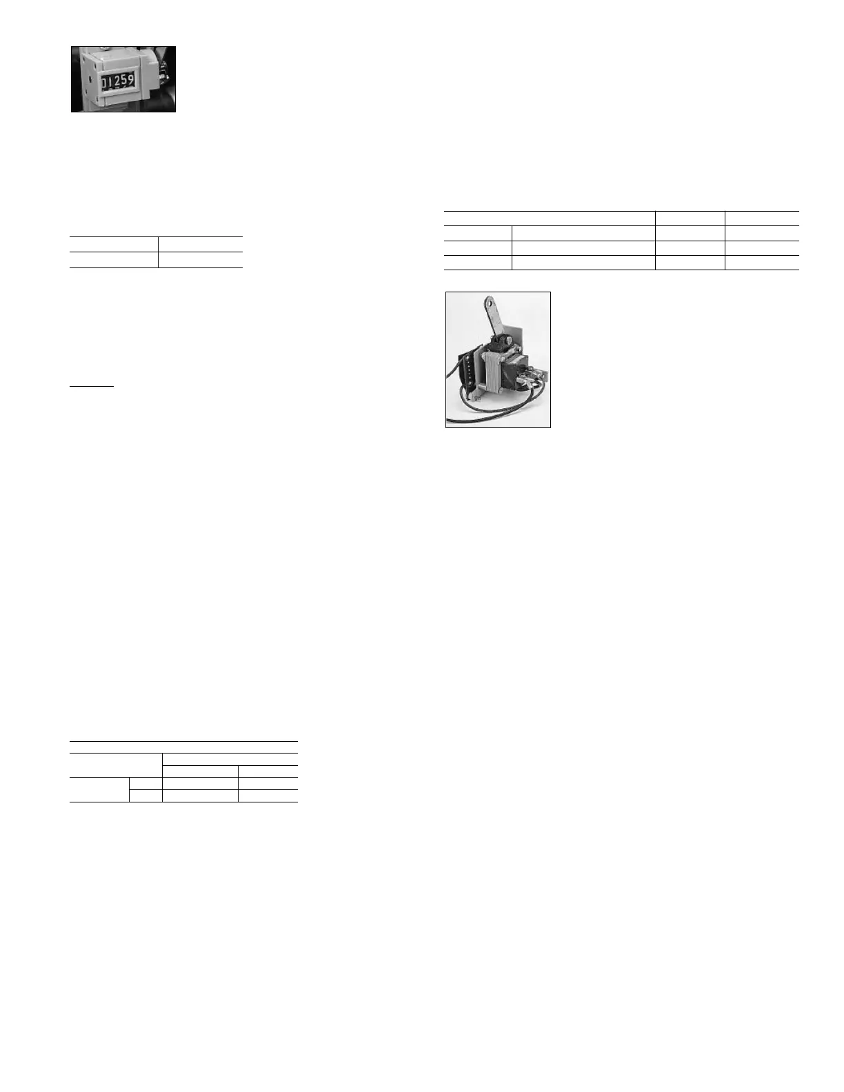
Remote Close Accessory with One-Shot Electronic Close
Circuit – Field installable kit available (Breaker accessory)
The remote close accessory is an electrically operated solenoid,
which when energized, closes the breaker. It is suitable for
control interlock schemes in which manual closing capability
would not be convenient or would be too slow. It is an
optional accessory for a manually operated breaker but is
always supplied with electrically operated breakers. The
remote close accessory consists of the “one-shot” electronic
close circuit, with built-in anti-pump feature, and the closing
solenoid. The remote close accessory is continuously rated
and operates as follows.
Applying control voltage to the close circuit produces a
250msec pulse to the closing coil which in turn releases the
energy stored in the closing springs. The anti-pump feature
pr
ev
ents the br
eak
er fr
om r
epeatedly closing if the close signal
is maintained. A momentary close signal (1/2 second duration)
is sufficient to close the breaker — but if the close signal is
maintained while the br
eak
er is closed, the signal must be
removed and then reapplied in order to reclose the breaker.
R
eset time for the anti-pump circuit is approximately 2.5
seconds. For applications r
equiring rapid r
eclosur
e of a cir
cuit
breaker, a momentary close signal should be used. This allows
the anti-pump circuit to reset while the closing springs are
r
echar
ging and the br
eak
er is then r
eady to reclose without
any additional time delays. A close signal applied to a closed
breaker will provide a pulse to the close coil, but the closing
mechanism is mechanically block
ed ther
eby pr
eventing the
closing springs from discharging. The close signal must be
removed as stated above before the breaker can be reclosed.
Contr
ol pow
er r
equir
ements for electrically charging and
closing the breaker are shown in Tables 15.3 and 16.1.
Breaker Frame and Operation Normally Open Normally Closed
WP-08 / 16 / 20 Manually or Electrically Operated WPRCISFKIT1 WPRCISFKIT2
WP-32 / 40 / 50 Electrically Operated WPRCILFKIT1 WPRCILFKIT3
WP-32 / 40 / 50 Manually Operated WPRCILFKIT2 WPRCILFKIT4
Position Switch Ratings
Contr
ol Voltage
Rating (Amperes)
Non-inductive Inductive
AC - 60Hz
120 10 6
240 10 6
WP-08 / 16 / 20 WP-32 / 40 / 50
WPCTRSFKIT1 WPCTRLFKIT1