À
Br
eaker and fuse roll-out must be mounted in separate vertical sections
Á
81" depth av
ailable only when these devices ar
e used in a line-up with items identified with **
®
Section width can be increased for additional cable / conduit space. 22" sections can be incr
eased to 30" wide, 30" wide sections can be increased to 38" wide.
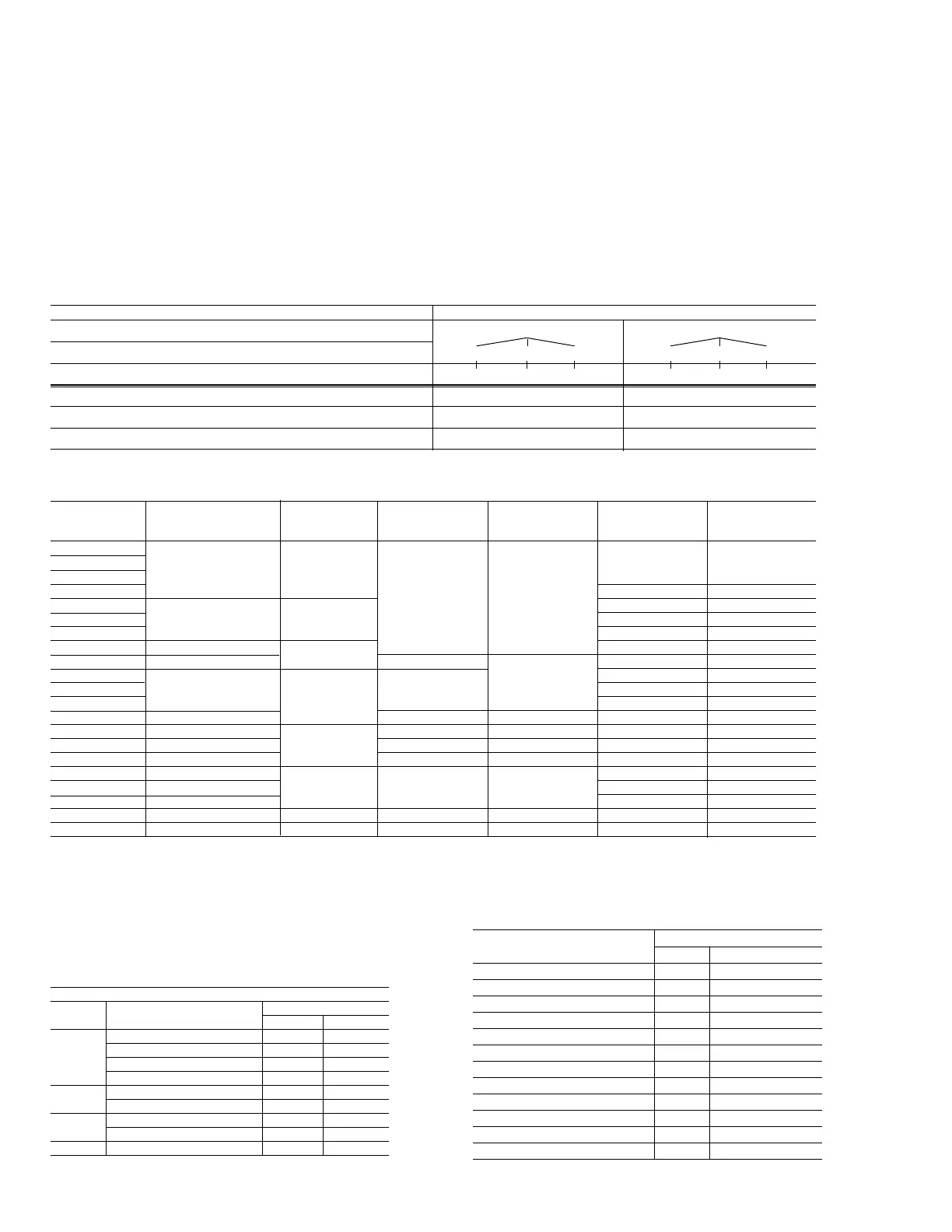
32
B
reaker type Device combination Frame size Breaker cubicle Minimum section Minimum equipment Optional
or bus rating (amperes) vertical height width
®
depth [Front/Rear equipment
(inches) (inches) compt] (inches) depth (inches)
WPS-08
WPH-08 800 60 [30 / 30] 67/74
WPX-08
WPF-08 21 22 67 [37 / 30] 74/81**
WPS-16 60 [30 / 30] 67/74
WPH-16 1600 60 [30 / 30] 67/74
WPF-16 67 [37 / 30] 74/81**
WPS-20 60 [30 / 30] 67/74
WPS-20 with fuse roll-out 2000 56 60 [30 / 30] 67/74/81
Á
WPS-32 30 60 [30 / 30] 67/74/81
Á
WPH-32
3200
35 60 [30 / 30] 67/74/81
Á
WPX-32 60 [30 / 30] 67/74/81
Á
WPS-32 with fuse roll-out 84 38 60 [30 / 30] 67/74/81
Á
WPS-40 35 30 60 [30 / 30] 67/74/81
Á
WP
X-40 4000 35 30 60 [30 / 30] 67/74/81
Á
WPS-40 with f
use roll-out 84 38 67 [37 / 30] 74/81**
WPS-50
74 [37 / 37] 81**
WPX-50
5000
35 38 74 [37 / 37] 81**
WPS-50 with fuse roll-out
À
74 [37 / 37] 81**
1600-4000A main bus rating
—
—
—
60 [30 / 30]
67/74
5000A main bus rating
—
—
—
67 [30 / 37] 74/81
Á
Enclosure type Available depth options
F
ront compartment 30” 37”
R
ear compartment (Std depth or 7” or 14” rear extension) 30” (std) 37” (7” ext)44” (14” ext) 30” (std) 37” (7” ext)44” (14” ext)
I
ndoor (total indoor frame depth) 60” 67” 74” 67” 74” 81”
Outdoor (total indoor frame depth) 60” 74”
W
a
lk-in (total enclosure depth) 108” 122”
Non-walk-in (total enclosure depth) 68” 82”
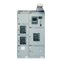
Sizing and dimensional data
Typical AC switchgear sections, 635V maximum,
50/60 Hz
S
witchgear section and line-up sizing
AKD-10 indoor low voltage switchgear height is 92" (97" over
t
he top wiring trough and 103.5" over the optional breaker
hoist). The available breaker stacking space is 84". Optional
78"-high indoor equipment with a breaker stacking space of
70" is also available (contact factory for details).
Breaker frame size and type determine the width of the
breaker sections and also the minimum depth of the
switchgear line-up. Refer to Tables 31.1 and 31.2 for properly
sizing AKD-10 line-ups. The depth of the entire line-up is
d
etermined by the deepest device in the line-up. For example,
a line-up with a WPS-20 breaker with a fuse roll-out (depth -
6
0") and WPF-08 breakers (depth - 67") would be a minimum
of 67" deep — the WPF-08 being the deepest device. Also
refer to the section arrangements on the following pages for
available breaker stacking configurations.
Table 32.1 Enclosure depth options
Table 32.2 AKD-10 Switchgear section sizing
Table 32.3 Switchgear weights
Procedur
e:
A)
Add the weight of ev
ery v
er
tical section in the lineup
B) Add the weight of each breaker and fuse roll-out in the lineup
À Also includes number of fuse roll-outs in the vertical section.
Table 32.4 WavePro breaker and fuse roll-out weights
Device
Net Weight, lb. [kg]
Manual Electrical
WPS / WPH-08 175 [79] 180 [82]
WPX-08 210 [95] 215 [98]
WPF-08 220 [100] 225 [102]
WPS / WPH-16 210 [95] 215 [98]
WPF-16 280 [127] 285 [129]
WPS-20 220 [100] 225 [102]
WPS / WPH / WP
X-32
490 [222] 500 [227]
WPS / WPX-40 535 [243] 545 [247]
WPS / WPX-50 600 [272] 610 [277]
2000/3200A Fuse Roll-out (WP32FRE) 330 [150] 3 Fuses – add 75 [34]
4000A Fuse Roll-out (WP40FRE) 335 [152] 3 Fuses – add 90 [41]
5000A Fuse Roll-out (WP50FRE) 345 [156] 3 Fuses – add 90 [41]
Vertical section weights, Lb. [Kg]
Section
width
# of br
eak
er compar
tments
À
in v
er
tical section
Enclosure type
Indoor Out
door
22"
1 940 (426) 1610 (730)
2 1100 (499) 1770 (803)
3 1270 (576) 1940 (880)
4 1440 (653) 2110 (957)
30"
1 1300 (590) 2100 (953)
2 1400 (635) 2300 (1043)
38"
1 1660 (753) 2600 (1179)
2 1900 (862) 2830 (1284)
22" or 30" Auxiliar
y section
1170 (531) 1800 (816)