31
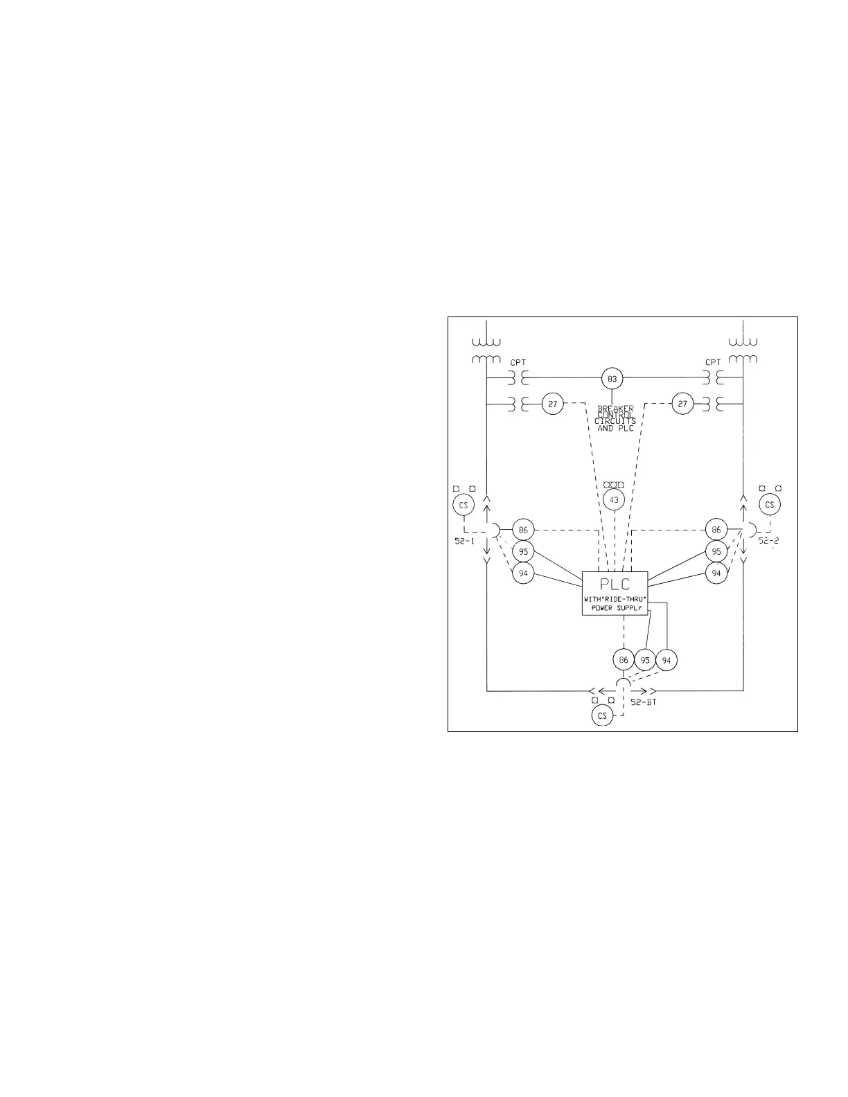
Automatic transfer (throwover) equipment
Relay and control equipment can be provided to maximize
continuity of service to a switchgear load bus by transferring
the load bus to an alternate or emergency power source in
the event of problems with the primary power source
(
undervoltage, loss of phase, etc.). Detection is typically pro-
vided by voltage relays (single- or three-phase undervoltage,
phase sequence/undervoltage, voltage unbalance, or a
combination of these). Breaker close and trip sequences may
be executed by hard-wired relay logic for simple transfer
schemes involving 2 or 3 circuit breakers. A programmable
logic controller (PLC) can be used for more complex transfer
schemes and provides maximum flexibility for modifications
to the control sequence without the addition of relays, switches,
and control wiring.
Interposing relays are provided for interfacing the PLC outputs
with the circuit breaker close and trip circuits. If the control
power source for the PLC is AC derived from within the
switchgear, a dedicated power supply is provided for the PLC
to ride through any momentary switching of the control power
sour
ces. The PLC programs are executed without interruption
during an undervoltage (or loss of phase) condition.
After the undervoltage (or loss of phase) condition has been
corrected, return to normal can be manual or automatic with
a time delay. A closed transition with momentary paralleling
can be provided as an option for return to normal and/or for
maintenance of the main and bus tie breakers (synchronism
check relay may be required).
Interlocking
WavePro
™
power circuit breakers can be interlocked in several
ways to prevent closing one breaker until another breaker is
open. Manually and electrically operated breakers can be
supplied with one single- or double-barrel key interlock
mounted in the breaker compartment. Key interlocks may
be used to pr
ev
ent paralleling sources in a double-ended
switchgear line-up. Only two keys are used for the three
interlocked breakers (two main and one tie). The interlock
without a key keeps the breaker mechanically trip-free, thus
allowing only two of the thr
ee br
eakers to be closed at any
given time.
K
ey interlocks can also be pr
ovided on substation main sec-
ondary breakers for interlocking with a transformer primary
air switch. Operation of the primary air switch (open or close)
is block
ed until the main secondar
y breaker is opened and
locked out. The key from the main breaker interlock is then
removed and inserted in the primary switch interlock thus
allowing operation of the switch.
Electrical interlocks
In lieu of mechanical k
ey interlocks, electrically operated
breakers can be provided with hard-wired electrical interlocking
using a combination of breaker auxiliary contacts (MOC) and
position switch contacts (T
OC). These contacts are wired in
the breaker close circuits such that closing of a tie breaker,
for example, is blocked or disabled until one of the main
breakers is opened. The position switch contacts allow normal
operation of the breakers during maintenance situations
where one or more of the interlocked breakers may be
racked out to the TEST or DISCONNECT position or withdrawn
f
rom the compartment.
A
form of electrical interlocking can also be provided on
manually operated breakers for control situations that
require an electrical contact closure before closing the
breaker. The electric lockout option on the circuit breaker
blocks operation of the closing mechanism until the coil of
the electric lockout is energized. De-energizing this coil after
the breaker is closed does not trip the breaker.
PLC Transfer Scheme Inputs & Outputs
PLC inputs
• Source voltage status (as sensed by the voltage relays)
• Main and tie breaker status (open, closed, tripped on fault)
• Main and tie breaker drawout position (connected, test/disconnect)
• Transfer system status (automatic/manual)
PLC outputs
• Close signal to main and bus tie br
eak
er
s
• Trip signal to main and bus tie breakers
•
Additional outputs and indicating lights can be provided for local identification
of transfer scheme status (auto-blue/manual-white) and PLC fault (amber)
Basic features of the PLC logic
• Interlocking of the main and bus tie breakers to prevent paralleling sources
• Time delay for initiating a transfer upon an undervoltage (or loss of phase)
condition
• Blocking transfer if either of the main or bus tie breakers trips due to a fault