17
Refer to Tables 16.1 and 16.2 for spring charging motor
operating characteristics.
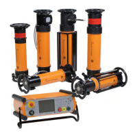
Test kit – (Equipment accessory)
T
he test kit, catalog number TVRMS2, is a portable, battery-or
ac-powered unit that is used for trip unit health checks and
a
lso provides functional trip and no-trip tests of the trip unit.
It can be used to defeat the ground fault function of the trip
unit when performing high current tests on the circuit breaker.
The test kit supplies 24Vdc auxiliary power for cold set-up and
viewing of trip targets on trip units not equipped with on-board
batteries. The display on the test kit can be used to verify
pickup and delay settings that have been programmed into
the trip unit. This test kit is designed for use with all Power+
™
,
MicroVersaTrip Plus
™
and MicroVersaTrip PM
™
trip units.
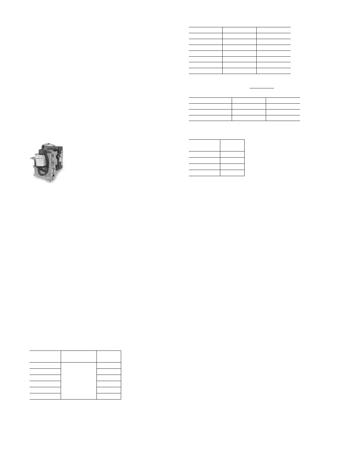
Undervoltage Device – Field installable kit available
(Breaker accessory)
The undervoltage device protects against harmful drops or
complete loss of voltage by automatically tripping the breaker.
The undervoltage device can be used to sense the drop or loss
of bus voltage through the use of voltage transformers or it can
monitor a control voltage source. This device is set to pick-up
at approximately 85% of rated voltage and will drop out
instantaneously between 30 and 60% (nonadjustable) of rated
voltage. An electronic module on the undervoltage device
provides accurate and repeatable operating characteristics.
The undervoltage device is available with an optional static time
delay unit
. This unit offers a field-adjustable two- to six-second
delay between undervoltage occurrence and breaker trip, thus
preventing potential nuisance tripping due to momentary loss
of voltage. The time delay unit is mounted externally to the
breaker. It is rated 125Vdc or 250Vdc or 208/240Vac, 50/ 60Hz.
For any other AC source voltage, a control power transformer
with a 240v secondary, rated at least 100VA, is required. Refer
to Table 17.1 for undervoltage device operating characteristics.
T
able 17.1
Under
v
oltage device operating characteristics
Table 17.2 Field Installable Undervoltage Device Kit catalog numbers
Table 17.3 Field Installable Time Delay Undervoltage Device Kit
catalog numbers (order Static Time Delay Unit separately)
Table 17.4 Static Time Delay catalog numbers
Repetitive duty
Circuit breakers are designed primarily to perform the func-
tion of circuit interruption under short-circuit conditions.
Nevertheless, modern circuit breakers’ mechanisms are
capable of many operations under full-load operation and
in-rush conditions such as those encountered in motor starting
applications. Industry standards have been established for
the minimum performance, as indicated in Table 18.1. With
adequate maintenance, GE breakers can be expected to
exceed the standards. WavePro
™
breakers have been designed
and tested to allow the user to extend the normal maintenance
service interval up to two times the ANSI recommendation —
a significant benefit for continuous process and 7-X-24
operations. See T
able 18.1 for additional information.
P
ower-operated circuit breakers, when operating under
usual ser
vice conditions, shall be capable of operating the
number of times specified in the following table. The operat-
ing conditions and the permissible effect of such operations
upon the br
eak
er ar
e listed in T
able 18.1 and the footnotes.
For instance, the breaker should be operated with rated
control voltage applied. The fr
equency of operation should
not exceed 20 in 10 minutes or 30 in an hour (r
ectifier
s or
other auxiliary devices may further limit the frequency of
operation). Servicing consisting of adjusting, cleaning, lubri
-
cating, tightening, etc., as r
ecommended by the maintenance
manual, is to be done at no greater interval than shown in
the column titled “Number of operations betw
een servicing”
in T
able 18.1. No f
unctional par
ts should r
equir
e r
eplace-
ment during the listed operations. The circuit breaker should
be in condition to carr
y its rated continuous curr
ent at rated
maximum v
oltage and per
form at least one opening operation
at rated short-circuit current. After completion of this series
of operations, f
unctional part replacement and general servicing
may be necessar
y.
N
ominal
control voltage
C
atalog
number
125Vdc TAKYUVT-1
250Vdc TAKYUVT-2
240Vac TAKYUVT-4
208Vac TAKYUVT-5
Control voltage WP-08 / 16 / 20 WP-32 / 40 / 50
208/240Vac 50/60Hz WPUVSFTD240 WPUVLFTD240
125Vdc WPUVSFTD125 WPUVLFTD125
2
50Vdc
W
PUVSFTD250
W
PUVLFTD250
Control voltage WP-08 / 16 / 20 WP-32 / 40 / 50
1
20Vac 50/60Hz
W
PUVSF56120
W
PUVLF56120
240Vac 50/60Hz WPUVSF56240 WPUVLF56240
24Vdc WPUVSFDC024 WPUVLFDC024
48Vdc WPUVSFDC048 WPUVLFDC048
1
10Vdc
W
PUVSFDC110
W
PUVLFDC110
125Vdc WPUVSFDC125 WPUVLFDC125
250Vdc WPUVSFDC250 WPUVLFDC250
Nominal
control voltage
Operating
voltage range
Holding
current, A
120Vac
Pick
up at 80% of
nominal contr
ol
v
oltage, drop out at
30-60% (non-adj)
of nominal contr
ol
voltage
0.15
240Vac 0.07
24Vdc 0.58
48V
dc
0.32
110/125V
dc
0.15
250Vdc 0.07