58
equipped with a rugged guide bar that will ensure alignment
of the primary and secondary disconnects as the breaker is
being racked into the test and connect positions. Drawout
breakers shall be equipped with wheels that will allow the
b
reaker to be rolled into cubicle once it is installed on the
drawout rails.
Standard mechanical interlocks shall be provided to prevent
moving the breaker from the connect, test, or disconnect
position unless the breaker main contacts are open. The
breaker shall be prevented from being closed during any
racking
operation and shall remain trip-free except when it is in the
test or connect positions. A mechanical interlock shall dis-
charge any energy stored in the closing springs before the
breaker can be withdrawn from its cubicle. A test position
shall be provided to permit operating the breaker while it is
disconnected from power circuit.
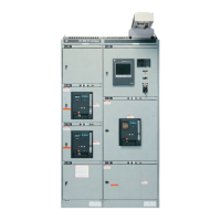
Detailed specifications
This specification covers GE WavePro
™
low voltage power
circuit breakers, types WPS, WPH, WPX, WPF.
The continuous current frame ratings shall be 800, 1600,
2000, 3200, 4000, 5000 amperes.
Circuit breakers shall be manually or electrically operated as
shown on the drawings.
Control voltage for electrically operated breakers shall be
___________volts <ac> <dc>
System voltage ______volts ac <50> <60> Hz
3Ph <3W> <4W>
Circuit breaker RMS symmetrical interrupting rating __kA
at ___volts
Circuit breakers shall be equipped with the following
accessories:
•
Auxiliary switch <3NO/3NC>, <6NO/6NC> contacts.
• Shunt trip, voltage ________.
• 2nd shunt trip, voltage _______. (800-4000A frames only)
•
Underv
oltage r
elease, voltage ________. <with time delay>
•
Electric lockout device to disable manual closing,
voltage _________.
•
Bell alarm <with> <without> lockout
, tw
o-SPD
T contacts
and mechanical tar
get
, r
esettable fr
om the fr
ont of the
breaker.
•
Non-r
esettable operations counter
.
•
R
emote char
ge indicator contact (1-NO) for electrically
operated breakers only .
•
“Hidden-on” (limited access) close button.
•
R
emote close accessory for manually operated br
eak
er
s,
voltage _________.
•
Cir
cuit br
eakers equipped with non-communicating trip
units (P
ow
er+
™
or Micr
oV
er
saTrip Plus
™
) shall be “pow
er
management ready” to accept easy upgrade to
Micr
oV
ersaTrip PM
™
trip unit without modifications to the
cir
cuit br
eak
er
.
• A maintenance video tape shall be available for use as a
supplement to the breaker installation and maintenance
manuals. The video shall cover acceptance, installation
and operation of the breakers, safety features, accessory
r
emoval and replacement, arc chute removal/replacement
and contact inspection and maintenance.
Trip devices
Power+
™
trip unit
1. Each circuit breaker shall be equipped with a protective
trip unit system to open the breaker for overloads, short
circuits <and ground faults> as specified in the following
subparagraphs. The protective trip unit system shall consist
of a solid-state, microprocessor-based trip unit, current
sensors, trip actuator and interchangeable rating plugs.
2. As a minimum, the trip unit shall have the following features
and functions:
a. The housing shall be a metallic enclosure to protect
against magnetic interference, dust and other
contaminants.
b. The protective system shall have reliable programmable
controls with repetitive accuracy and precise unit settings.
Overcurrent characteristics (pickup and delay) shall be
selected via rotary switches with detented settings.
c. All current sensing shall employ true rms technology for
detecting overloads, <short time> overcurrent conditions
and <ground fault conditions>.
d. The optional Target Module shall be equipped with
long-life lithium batteries - with automatic time delay
shut-off feature - to provide observation of trip targets.
The Target Module and batteries shall not be required
for the trip unit to provide its protective functions.
e. UL listed and CSA certified field installable, interchange-
able rating plugs. It shall not be necessary to change or
remove the trip unit to change the trip rating. Rating plugs
shall contain rejection features to prevent installation of
a plug with an incorrect current sensor rating. Rating
plugs shall also be used to provide the trip unit with
ground fault protection. Rating plugs shall be av
ailable
with or without ground fault pickup and delay setting
switches. It shall be possible to add gr
ound fault pro-
tection to a trip unit by simply replacing the rating plug.
f
.
Integral test jack for connection of a batter
y pack or
test k
it to the breaker.
g.
(When specified) the gr
ound fault f
unction shall contain a
memor
y cir
cuit to integrate low lev
el ar
cing fault curr
ents
with time to sum intermittent ground fault current spikes.
h.
A cov
er with pr
ovisions for sealing the rating plug and
trip unit to mak
e the installation tamper-resistant. All
trip unit settings, ratings, and target information shall
be capable of being viewed with the cov
er in place.
i.
The unit shall be dual-rated for both 50Hz and 60Hz
operation. Noise immunity shall meet the requirements
of ANSI S
tandar
d C37.90.2
j.
The trip unit shall display trip tar
gets for longtime, shor
t
time, instantaneous and ground fault trips (with optional
T
ar
get Module)