EasyManua.ls Logo

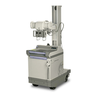
GE AMX-II

GE AMX-II
223 pages
To Next Page IconTo Next Page
To Previous Page IconTo Previous Page
Loading...
GENERAL
ELECTRIC
MEDICAL
SYSTEMS
AMX-Il
X-RAY
UNIT
1-981
OM
A0654E
UNIT
ON
CHARGE
ON
CHARGE
LAMP
LAMP
COMPLETE
LAMP
BATTERY
CONDITION
INDICATOR
KEYED
X-RAY
METER
GENERATOR
STANDBY
BATTERY
SWITCH
VOLTAGE
COMPENSATOR
KVP
SELECTOR
SWITCH
MAS
SELECTOR
SWITCH
“>
X-RAY
ON
LAMP
READY
LAMP
=
~
MAIN
POWER
hs
circuit
DIRECTION
ee
na
BREAKER
SELECTOR
ーー
パテ
ーー
с
e
UT
BRAKE
SWITCH
\
HANDLE
га
DRIVE
ASSIST
о
y
SPEED
BUTTON
ILLUSTRATION
1-2
23563210
CONTROL
FUNCTIONAL
DESCRIPTION
The
MAIN
POWER
CIRCUIT
BREAKER
disconnects
the
Battery.
It
must
be
ON
in
order
to
charge
the
unit,
drive
it
from
one
location
to
another,
and
make
exposures.
The
keyed
X-RAY
GENERATOR
STANDBY
SWITCH
is
turned
to
OFF
when
the
AMX-II
is
being
driven
or
is
not
in
use,
to
ON
for
exposures,
and
to
CHARGE
when
charging
the
batteries.
A
key
is
provided
for
this
switch
to
assure
that
only
authorized
personnel
operate
the
unit.
The
key
should
be
taken
out
of
the
socket
and
retained
by
the
designated
operator
immediately
after
a
scheduled
period
of
x-ray
operation.
The
BATTERY
CHARGER
recharges
the
internal
battery
from
any
115v
or
230v,
50-60
Hz
power
outlet
receptacle.
The
unit
may
not
be
driven
or
an
x-ray
exposure
cannot
be
made
when
the
battery
charger
plug
is
in
a
power
outlet
receptacle.
The
x-ray
unit
battery
should
be
charged
(as
described
under
OPERATION)
whenever
the
BATTERY
CONDITION
needle
enters
the
red
band.
It
should
be
allowed
to
charge
until
the
amber
CHARGE
COM-
PLETE
lamp
giows,
and
the
BATTERY
CONDITION
indicator
needle
is
in
the
green
band.
Typically,
the
battery
will
charge
from
too
low
(red
band)
to
full
charge
in
less
than
10
hours.
Since
the
charger
is
self-regulating,
it is
permissible
to
have
it
connected
to
power
indefinitely.
CAUTION:
ALWAYS
LOCATE
THE
UNIT
IN
A
WELL
VENTILATED
ROOM
WHEN
CHARGING
IT.
The
SPEED
CONTROL
will
vary
the
speed
of
the
unit
in
forward
or
reverse.
When
released,
it
will
return
to
the
zero
speed
position.
The
SAFETY
BUMPER,
located
on
the
front
of
the
unit,
will
disconnect
the
drive
motor
and
stop
the
unit
upon
impact
with
any
object.
The
DRIVE
ASSIST
BUTTON,
when
pressed,
will
increase
the
low
speed
torque
of
the
drive
motor.
It
is
a
spring
loaded
button
which
should
be
used
when
climbing
an
incline
or
when
moving
over
the
edge
of
carpeting
or
other
small
floor
discontinuities.

Related product manuals