EasyManua.ls Logo

GE AMX-II

GE AMX-II
223 pages
To Next Page IconTo Next Page
To Previous Page IconTo Previous Page
Loading...
GENERAL
ELECTRIC
MEDICAL
SYSTEMS
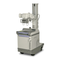
AMX-II
X-RAY
UNIT
7-1576
| |
SM
A0654E
SEC.
3
INVERTER
DRIVERS
From
lil.
6-2B
it
can
be
seen
that
the
DC
battery
voltage
is
fed
to
the
60
Hz
inverter
(Sec.
5)
where
it
is
“inverted”
into
square
wave
AC
power.
The
inverter
driver
controls
the
frequency
at
which
the
inverter
operates.
The
inverter
driver
output
coupler
(Sec.
4)
provides
a
peak
pulse
at
the
gate
of
the
SCR
for
reliable
triggering.
120
V
BATTERY
500
HZ
INVERTER
INVERTER
DRIVER
INVERTER
DRIVER
=
OUTPUT
COUPLER
—___=»—»
(SEE
SEC.
3)
(SEE
SEC.
4)
(SEE
SEC.
5)
ILLUSTRATION
6-2B
The
inverter
driver
consists
of
a
flip-flop
multivibrator
triggered
by
a
UJT
oscillator.
The
60
Hz
inverter
driver
is
the
same
as
the
500
Hz
inverter
driver
except
the
resistor
and
capacitor
in
the
oscillator
has
been
changed
to
provide
the
different
frequency.
_
The
schematic
reference
for
the
500
Hz
inverter
is
sheet
5,
Chapter
7.
A
simplified
circuit
is
shown
in
Illustration
6-3.
The
UJT
oscillator
provides
a
source
of
short
precisely
timed
negative
pulses
with
a
period
determined
by
C21
and
R18
plus
R22.
R18
is
adjusted
to
obtain
500
Hz.
The
pulses
are
coupled
to
the
common
emitter
resistor
(R15)
of
a
transistor
flip-flop
circuit
(Q19
and
020).
Details
of
flip-flop
circuit
operation
may
be
found
in
the
GE
Transistor
Manual,
Sixth
Edition
under
Square
Wave
Inverter
Drive
Circuits.
The
output
of
the
flip-flop circuit
is
amplified
by
Q49
and
Q45
and
coupled
to
the
inverter
by
transformer
3T1.
In
inverter
circuits
it
is
important
that
one
SCR
be
allowed
sufficient
time
to
turn
off
before
the
other
is
placed
in
conduction.
Therefore,
the
inverter
driver
circuits
are
designed
to
have
a
slight
delay
between
the
termination
of
one
pulse
and
the
start
of
the
next
as
specified
below.
The
500
Hz
inverter
SCR
gate
voltages
are
shown
in
W-24.
The
delay
can
be
seen
by
observing
that
one
pulse
in
W-24A
terminates
on
the
left
side
of
the
centerline
graticule
and
the
next
pulse
in
W-24B
starts
to
the
right
of
the
centerline
graticule.
An
expanded
view
would
appear
as
shown
in
Illustration
6-4.

Related product manuals