EasyManua.ls Logo

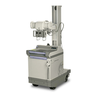
GE AMX-II

GE AMX-II
223 pages
To Next Page IconTo Next Page
To Previous Page IconTo Previous Page
Loading...
GENERAL
ELECTRIC
MEDICAL
SYSTEMS
AMX-il
X-RAY
UNIT
7-1576
. '
SM
AO654E
FILLER
CAP
VENT
PLUG
BAFFLE
.
LL
CASE
(9.53mm)
IN
THE
FULLY
CHARGED
CONDITION
ELECTROLYTE
SHOULD
BE
APPROXIMATELY
3/8"
(9.53mm)
ABOVE
BOTTOM
OF
BAFFLE.
LEVEL
OF
ELECTROLYTE
IN
TYPICAL
CELL
16948-R11
LEVEL
OF
ELECTROLYTE
IN
TYPICAL
CELL
ILLUSTRATION
3-15
6-4
Battery
installation
in
Unit
1.
Disconnect
the
battery
leads
and
jumpers
from
each
cell
group.
(Be
sure
to
use
the
protective
barriers
per
Section
6-1,
Step
12.)
2.
Fold
back
the
Mylar
covering
the
battery
compartment.
3.
Slide
one
30-cell
group
in
the
right
side
of
the
battery
compartment.
Before
pushing
it
all
the
way
in,
check
that
protective
barriers
are
installed.
Connect
the
lead
out
of
the
top
main
circuit
breaker
that
is
labelled
(+)
to
the
right
front
corner
terminal
(shown
as
F
in
Illustration
3-14)
of
the
battery
pack.
4.
Slide
another
30-cell
group
into
the
left
side
of
the
battery
compartment.
Before
pushing
it
all
the
way
in,
install
the
protective
barriers,
then
connect
the
lead
on
the
side
of
the
main
power
circuit
breaker
that
is
labelled
(-)
to
the
front
left
corner
terminal
(A
in
Illustration
3-14)
of
the
battery
pack.
5.
Slide
the
remaining
30-cell
group
into
the
center
of
the
battery
compartment.
Insert
two
7-3/4”
x
16-1/4”
(2.12
m
x
4.91
m)
red
insulator
boards
(furnished)
between
the
right
and
center
and
two
others
between
the
left
and
center
ceil
group.
These
are
to
prevent
the
battery
from
sliding
around.
6.
Two
No.
6
AWG
leads
6”
(152.4
mm)
long
are
furnished.
Use
them
to
interconnect
the
left,
right
and
center
battery
packs.
Install
the
protective
barriers,
Illustration
3-13,
Connect
B
to
C
and
D
to
E
as
shown
in
Illustration
3-14.
After
the
connection,
push
the
Temflex
sleeving
over
the
solderiess
terminal
lug
of
each
end
of
each
jumper.
See
Illustration
3-14.
7.
Place
the
Mylar
cover
over
the
battery
compartment
and
reinstall
the
battery
retainer
plate
and
the
kick
panel.
3-22

Related product manuals