10-4 B30 Bus Differential System GE Multilin
10.2 ZONING AND DYNAMIC BUS REPLICA 10 APPLICATION OF SETTINGS
10
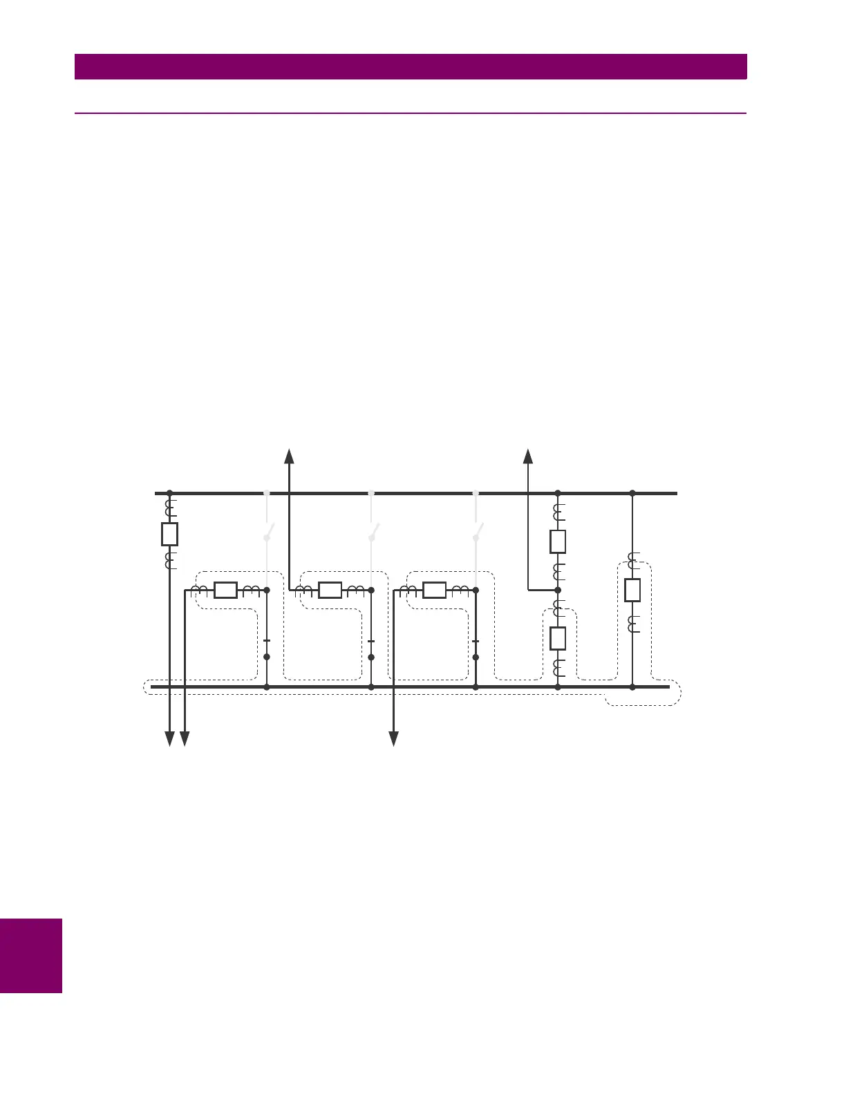
10.2.3 SOUTH BUS ZONE
The South bus differential zone is bounded by the following CTs: CT-2 (if S-2 closed), CT-3 (if S-4 closed), CT-4 (if S-6
closed), CT-6 and CT-7. The South bus protection should operate the following breakers: B-2 (if S-2 closed), B-3 (if S-4
closed), B-4 (if S-6 closed), B-6 and B-7.
Consequently, the second B30 for the South bus should be wired and configured as follows:
• CT-2 currents should be configured as SRC 1 and used as the source 1A of the bus differential zone 1 together with
the status of the S-2 switch.
• CT-3 currents should be configured as SRC 2 and used as the source 1B of the bus differential zone 1 together with
the status of the S-4 switch.
• CT-4 currents should be configured as SRC 3 and used as the source 1C of the bus differential zone 1 together with
the status of the S-6 switch.
• CT-6 currents should be configured as SRC 4 and used as the source 1D of the bus differential zone 1 together with
the FlexLogic “On” constant for the status.
• CT-7 currents should be configured as SRC 5 and used as the source 1E of the bus differential zone 1 together with
the FlexLogic “On” constant for the status.
• The trip signal should be routed directly to the B-6 and B-7 breakers while it should be supervised by the status of S-2,
S-4 and S-6 for the B-2, B-3 and B-4 breakers, respectively.
Figure 10–4: SOUTH BUS ZONE
836734A1.CDR
NORTH BUS
SOUTH BUS
CT-7
CT-8
B-7
B-5
B-6
CT-5
CT-6
S-5
S-6
B-4CT-4
S-3
S-4
B-3CT-3
S-1
S-2
B-2CT-2
CT-1
B-1
C-1 C-2 C-4
C-3 C-5

 Loading...


