GE Multilin B30 Bus Differential System 5-7
5 SETTINGS 5.1 OVERVIEW
5
The UR platform allows for a maximum of six sets of three-phase voltages and six sets of three-phase currents. The result
of these restrictions leads to the maximum number of CT/VT modules in a chassis to three. The maximum number of
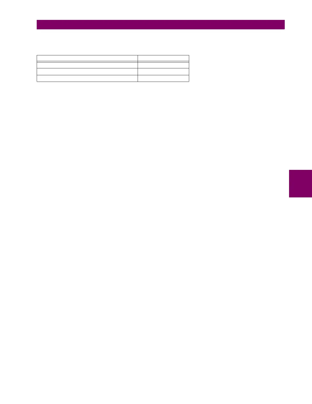
sources is six. A summary of CT/VT module configurations is shown below.
c) CT/VT INPUT CHANNEL CONFIGURATION
Upon relay startup, configuration settings for every bank of current or voltage input channels in the relay are automatically
generated from the order code. Within each bank, a channel identification label is automatically assigned to each bank of
channels in a given product. The bank naming convention is based on the physical location of the channels, required by the
user to know how to connect the relay to external circuits. Bank identification consists of the letter designation of the slot in
which the CT/VT module is mounted as the first character, followed by numbers indicating the channel, either 1 or 5. See
the HardFiber instruction manual for designations of HardFiber voltage and current banks.
For three-phase channel sets, the number of the lowest numbered channel identifies the set. For example, F1 represents
the three-phase channel set of F1/F2/F3, where F is the slot letter and 1 is the first channel of the set of three channels.
Upon startup, the CPU configures the settings required to characterize the current and voltage inputs, and will display them
in the appropriate section in the sequence of the banks (as described above) as follows for a maximum configuration: F1,
F5, M1, M5, U1, and U5.
ITEM MAXIMUM NUMBER
CT/VT Module 3
CT Bank (3 phase channels, 1 ground channel) 6
VT Bank (3 phase channels, 1 auxiliary channel) 3