GE Multilin B30 Bus Differential System 8-1
8 THEORY OF OPERATION 8.1 INTRODUCTION
8
8 THEORY OF OPERATION 8.1INTRODUCTION 8.1.1 BUS DIFFERENTIAL PROTECTION
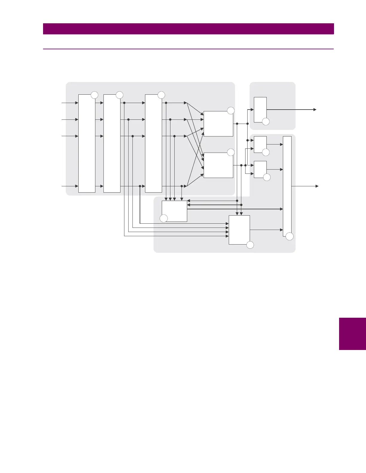
Referring to the figure below, input currents defining (through the dynamic bus replica) the bus differential zone are
received by the B30 from current transformers (CTs) associated with the power system.
Figure 8–1: BUS DIFFERENTIAL PROTECTION BLOCK DIAGRAM
The currents are digitally pre-filtered (Block 1) in order to remove the decaying DC components and other signal distortions.
The filtered input signals are brought to a common scale taking into account the transformation ratios of the connected CTs
(Block 2). See section 8.2: Dynamic Bus Replica for details.
Phasors of the differential zone currents are estimated digitally (Block 3) and the differential (Block 4) and restraining (Block
5) signals are calculated. See section 8.3: Differential Principle for details.
The magnitude of the differential signal is compared with a threshold and an appropriate flag indicating operation of the
unbiased bus differential protection is produced (Block 6).
The magnitudes of the differential and restraining currents are compared and two auxiliary flags that correspond to two spe-
cifically shaped portions of the differential operating characteristic (DIF1 and DIF2) are produced (blocks 7 and 8). The
characteristic is split in order to enhance performance of the relay by applying diverse security measures for each of the
regions. See section 8.3: Differential Principle for details.
The directional element (Block 10) supervises the biased differential characteristic when necessary. The current directional
comparison principle is used that processes phasors of all the input currents as well as the differential and restraining cur-
rents. See section 8.4: Directional Principle for details.
The saturation detector (Block 9) analyzes the differential and restraining currents as well as the samples of the input cur-
rents. This block sets its output flag upon detecting CT saturation. See section 8.5: Saturation Detector for details.
The output logic (Block 11) combines the differential, directional and saturation flags into the biased differential operation
flag. The applied logic enhances performance of the relay while keeping an excellent balance between dependability/speed
and security. See section 8.6: Output Logic and Examples for details.
Measuring Unit
Biased Differential
Unit
Unbiased Differential
Unit
Pre-Filtering
i
1
i
2
i
3
i
N
Ratio Matching and Scaling
Phasor Estimation
Differential
Current
Restraining
Current
Differential
Unbiased
DIF1DIF2
Directional
Element
Saturation
Detector
L
O
G
I
C
input currents
I
1
I
2
I
3
I
N
I
D
I
R
DIF
L
DIF
UNB
DIF
H
SAT
DIR
1 2 3
4
5
10
6
7
8
9
11
DIF
BIASED
836723A1.CDR