3-32 B30 Bus Differential System GE Multilin
3.3 DIRECT INPUT AND OUTPUT COMMUNICATIONS 3 HARDWARE
3
3.3DIRECT INPUT AND OUTPUT COMMUNICATIONS 3.3.1 DESCRIPTION
The direct inputs and outputs feature makes use of the type 7 series of communications modules, which allow direct mes-
saging between UR devices. These communications modules are outlined in the table later in this section.
The communications channels are normally connected in a ring configuration as shown in the following figure. The trans-
mitter of one module is connected to the receiver of the next module. The transmitter of this second module is then con-
nected to the receiver of the next module in the ring. This is continued to form a communications ring. The figure illustrates
a ring of four UR-series relays with the following connections: UR1-Tx to UR2-Rx, UR2-Tx to UR3-Rx, UR3-Tx to UR4-Rx,
and UR4-Tx to UR1-Rx. A maximum of 16 URs can be connected in a single ring
Figure 3–29: DIRECT INPUT AND OUTPUT SINGLE CHANNEL CONNECTION
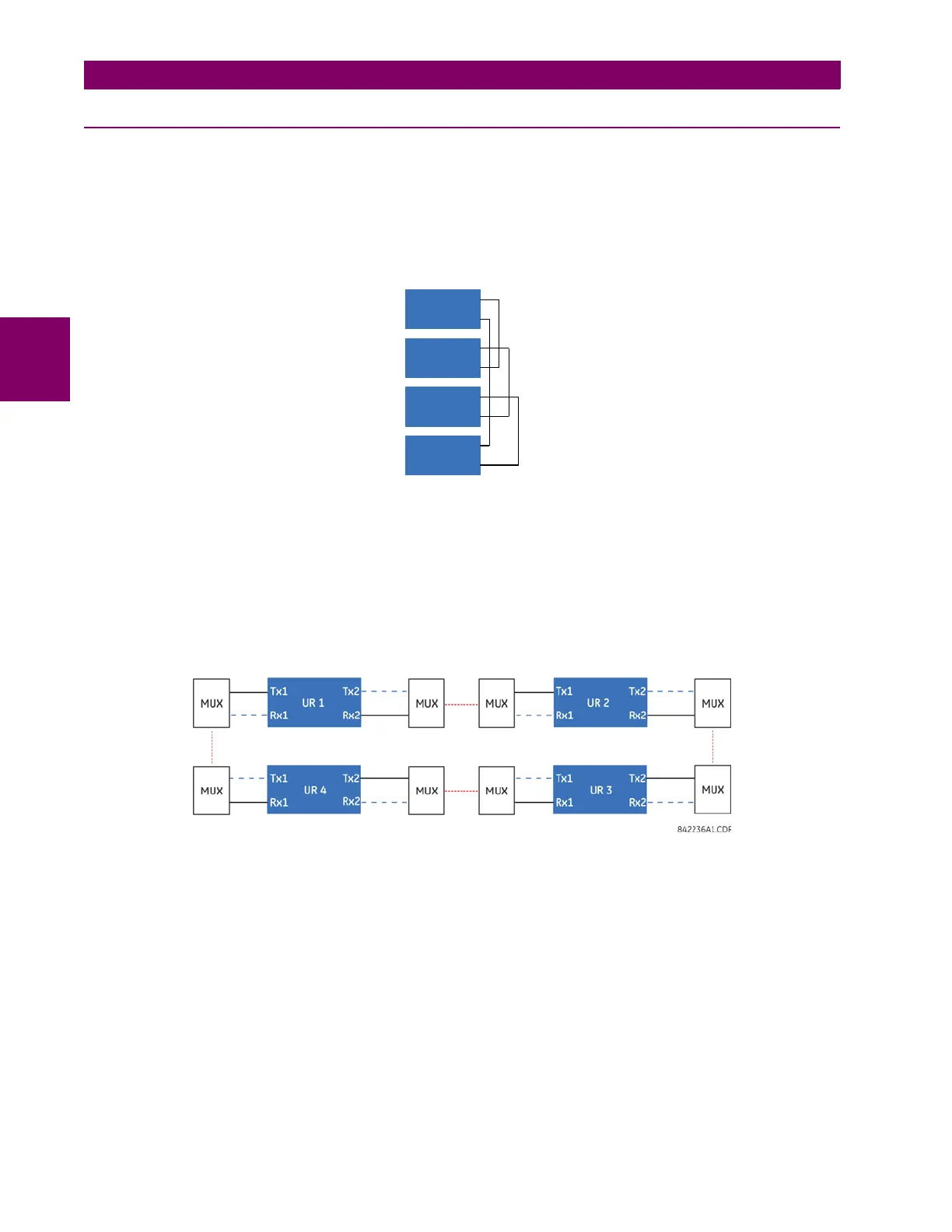
IRC modules with protocol C37.94 and G.703 are designed for back-to-back communication connections, so the ring con-
figuration shown in the previous figure does not apply. To establish inter-relay communication in more than two URs, you
need to have two channel IRC module and enable DIRECT I/O CHANNEL CROSSOVER function in all relays, as shown in
the next figure. This configuration can be expanded to 16 URs, and this configuration does not provide redundancy ring
since both channels are made into single ring by the channel crossover function. As per the figure Typical Pin Interconnec-
tion between Two G.703 Interfaces later in this chapter, the clock is supplied typically by multiplexer (MUX) and all URs are
in Loop Timing Mode. If there is no MUX, then UR1 and UR3 can be in Internal Timing Mode and UR2 and UR4 can be in
Loop Timing Mode. That is, connected channels must have opposite timing modes.
Figure 3–30: RING CONFIGURATION FOR C37.94 MODULE (CONCEPT ALSO APPLIES TO G.703)
842006A2.CDR
Tx
Tx
Tx
Tx
UR 1
UR 2
UR 3
UR 4
Rx
Rx
Rx
Rx