GE Multilin B30 Bus Differential System 3-33
3 HARDWARE 3.3 DIRECT INPUT AND OUTPUT COMMUNICATIONS
3
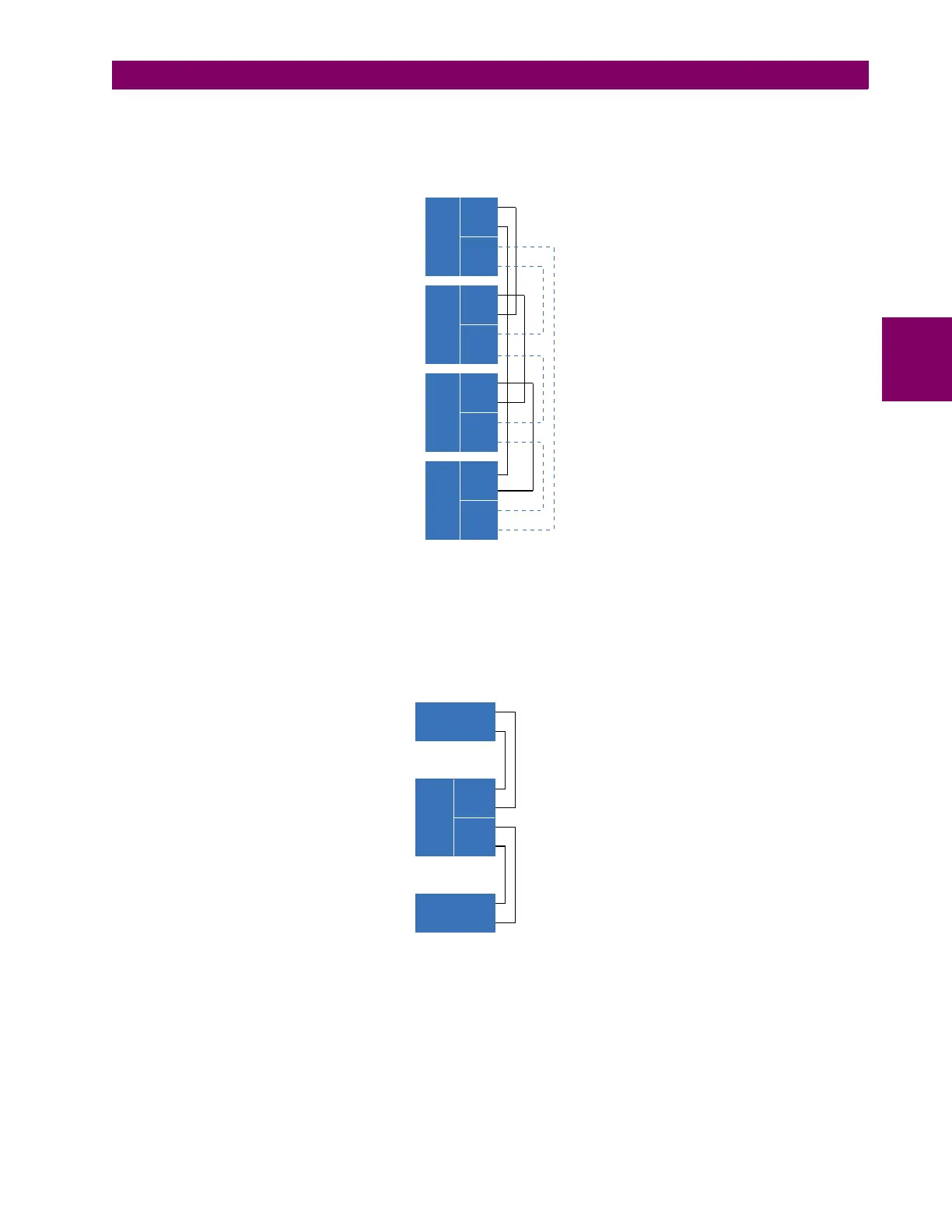
The interconnection for dual-channel type 7 communications modules is shown as follows. Two channel modules allow for
a redundant ring configuration. That is, two rings can be created to provide an additional independent data path. The
required connections are: UR1-Tx1 to UR2-Rx1, UR2-Tx1 to UR3-Rx1, UR3-Tx1 to UR4-Rx1, and UR4-Tx1 to UR1-Rx1
for the first ring; and UR1-Tx2 to UR4-Rx2, UR4-Tx2 to UR3-Rx2, UR3-Tx2 to UR2-Rx2, and UR2-Tx2 to UR1-Rx2 for the
second ring.
Figure 3–31: DIRECT INPUT AND OUTPUT DUAL CHANNEL CONNECTION
The following diagram shows the connection for three UR-series relays using two independent communication channels.
UR1 and UR3 have single type 7 communication modules; UR2 has a dual-channel module. The two communication chan-
nels can be of different types, depending on the Type 7 modules used. To allow the direct input and output data to cross-
over from channel 1 to channel 2 on UR2, the
DIRECT I/O CHANNEL CROSSOVER setting should be “Enabled” on UR2. This
forces UR2 to forward messages received on Rx1 out Tx2, and messages received on Rx2 out Tx1.
Figure 3–32: DIRECT INPUT AND OUTPUT SINGLE/DUAL CHANNEL COMBINATION CONNECTION
The inter-relay communications modules are available with several interfaces and some are outlined here in more detail.
Those that apply depend on options purchased. The options are outlined in the Inter-Relay Communications section of the
Order Code tables in Chapter 2. All of the fiber modules use ST type connectors.
842007A3.CDR
Tx1
UR 1
Tx2
Rx1
Rx2
Tx1
UR 2
Tx2
Rx1
Rx2
Tx1
UR 3
Tx2
Rx1
Rx2
Tx1
UR 4
Tx2
Rx1
Rx2
842013A2.CDR
Channel 1
Channel 2
Tx1
UR 2
Tx2
Rx1
Rx2
Tx
UR 1
Rx
Tx
UR 3
Rx