6-14 B30 Bus Differential System GE Multilin
6.3 METERING 6 ACTUAL VALUES
6
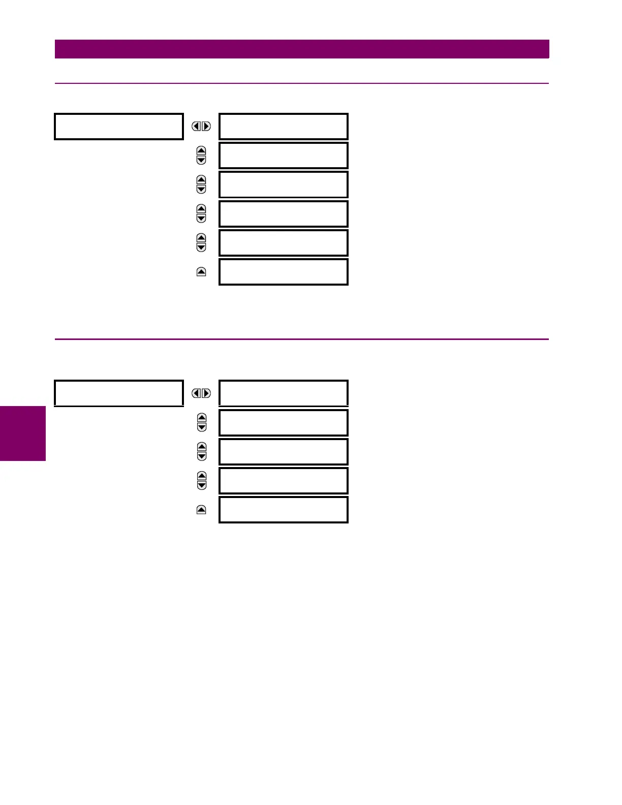
6.3.3 BUS ZONE
PATH: ACTUAL VALUES METERING BUS BUS ZONE 1
These values display the differential and restraint currents phasors for the bus zone. The magnitudes are displayed in pri-
mary amperes (see chapter 8: Theory of operation for additional details).
6.3.4 SOURCES
a) MAIN MENU
PATH: ACTUAL VALUES METERING SOURCE SRC1
This menu displays the metered values available for each source.
Metered values presented for each source depend on the phase and auxiliary VTs and phase and ground CTs assignments
for this particular source. For example, if no phase VT is assigned to this source, then any voltage, energy, and power val-
ues will be unavailable.
BUS ZONE 1
BUS 1 DIFF Iad:
0.000 A 0.0°
MESSAGE
BUS 1 REST Iar:
0.000 A 0.0°
MESSAGE
BUS 1 DIFF Ibd:
0.000 A 0.0°
MESSAGE
BUS 1 REST Ibr:
0.000 A 0.0°
MESSAGE
BUS 1 DIFF Icd:
0.000 A 0.0°
MESSAGE
BUS 1 REST Icr:
0.000 A 0.0°
SOURCE SRC 1
PHASE CURRENT
SRC 1
See page 6–15.
MESSAGE
GROUND CURRENT
SRC 1
See page 6–15.
MESSAGE
PHASE VOLTAGE
SRC 1
See page 6–16.
MESSAGE
AUXILIARY VOLTAGE
SRC 1
See page 6–16.
MESSAGE
FREQUENCY
SRC 1
See page 6–17.