GE Multilin B30 Bus Differential System 5-139
5 SETTINGS 5.6 GROUPED ELEMENTS
5
5.6.3 BUS DIFFERENTIAL
PATH: SETTINGS GROUPED ELEMENTS SETTING GROUP 1(6) BUS DIFFERENTIAL BUS ZONE 1(2) DIFFERENTIAL
Two zones of bus differential protection are provided. The operation of these elements is completely dependent on the
dynamic bus replica, which must be defined first. Both biased and unbiased bus differential protection functions are pro-
vided for the bus differential zone.
The biased bus differential function has a dual-slope operating characteristic (see figure below) operating in conjunction
with saturation detection and a directional comparison principle (see the Bus zone 1 differential scheme logic figure in this
section).
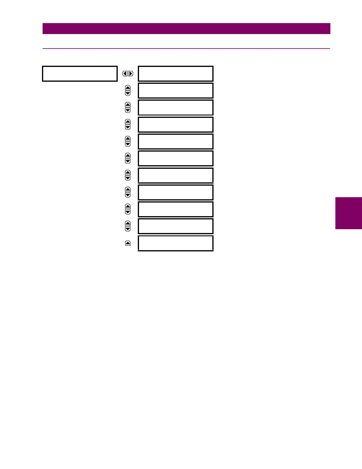
BUS ZONE 1
DIFFERENTIAL
BUS ZONE 1 DIFF
FUNCTION: Disabled
Range: Disabled, Enabled
MESSAGE
BUS ZONE 1 DIFF
PICKUP: 0.100 pu
Range: 0.050 to 6.000 pu in steps of 0.001
MESSAGE
BUS ZONE 1 DIFF
LOW SLOPE: 25%
Range: 15 to 100% in steps of 1
MESSAGE
BUS ZONE 1 DIFF
LOW BPNT: 2.00 pu
Range: 1.00 to 30.00 pu in steps of 0.01
MESSAGE
BUS ZONE 1 DIFF
HIGH SLOPE: 60%
Range: 50 to 100% in steps of 1
MESSAGE
BUS ZONE 1 DIFF
HIGH BPNT: 8.00 pu
Range: 1.00 to 30.00 pu in steps of 0.01
MESSAGE
BUS ZONE 1 DIFF
HIGH SET: 15.00 pu
Range: 0.10 to 99.99 pu in steps of 0.01
MESSAGE
BUS ZONE 1 DIFF
SEAL-IN: 0.400 s
Range: 0.000 to 65.535 s in steps of 0.001
MESSAGE
BUS ZONE 1 DIFF BLK:
Off
Range: FlexLogic operand
MESSAGE
BUS ZONE 1 DIFF
TARGET: Latched
Range: Self-reset, Latched, Disabled
MESSAGE
BUS ZONE 1 DIFF
EVENTS: Disabled
Range: Disabled, Enabled