EasyManuals Logo

GE b30 User Manual

GE b30
626 pages
To Next Page IconTo Next Page
To Previous Page IconTo Previous Page
Page #92 background imageLoading...
Page #92 background image
3-34 B30 Bus Differential System GE Multilin
3.3 DIRECT INPUT AND OUTPUT COMMUNICATIONS 3 HARDWARE
3
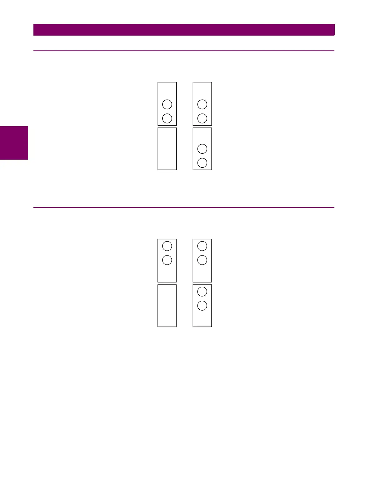
3.3.2 FIBER: LED AND ELED TRANSMITTERS
The following figure shows the configuration for the 7A, 7B, 7C, 7H, 7I, and 7J fiber-only modules.
Figure 3–33: LED AND ELED FIBER MODULES
3.3.3 FIBER-LASER TRANSMITTERS
The following figure shows the configuration for the 72, 73, 7D, and 7K fiber-laser modules.
Figure 3–34: 7X LASER FIBER MODULES
7A, 7B, and
7C modules
7H, 7I, and
7J modules
1 channel 2 channels
Rx1
Rx1
Rx2
Tx1 Tx1
Tx2
831719A3.CDR
1 channel 2 channels
Rx1 Rx1
Rx2
Tx1 Tx1
Tx2
831720A5.CDR
72 and 7D
modules
73 and 7K
modules

Table of Contents

Other manuals for GE b30

Questions and Answers:

Question and Answer IconNeed help?

Do you have a question about the GE b30 and is the answer not in the manual?

GE b30 Specifications

General IconGeneral
Modelb30
ManufacturerGE
Coil VoltageN/A (Solid State Relay)
Coil PowerN/A (Solid State Relay)
Mechanical LifeN/A (Solid State Relay)
Electrical LifeN/A (Solid State Relay)

Related product manuals