9-4 B30 Bus Differential System GE Multilin
9.2 ZONING AND DYNAMIC BUS REPLICA 9 APPLICATION OF SETTINGS
9
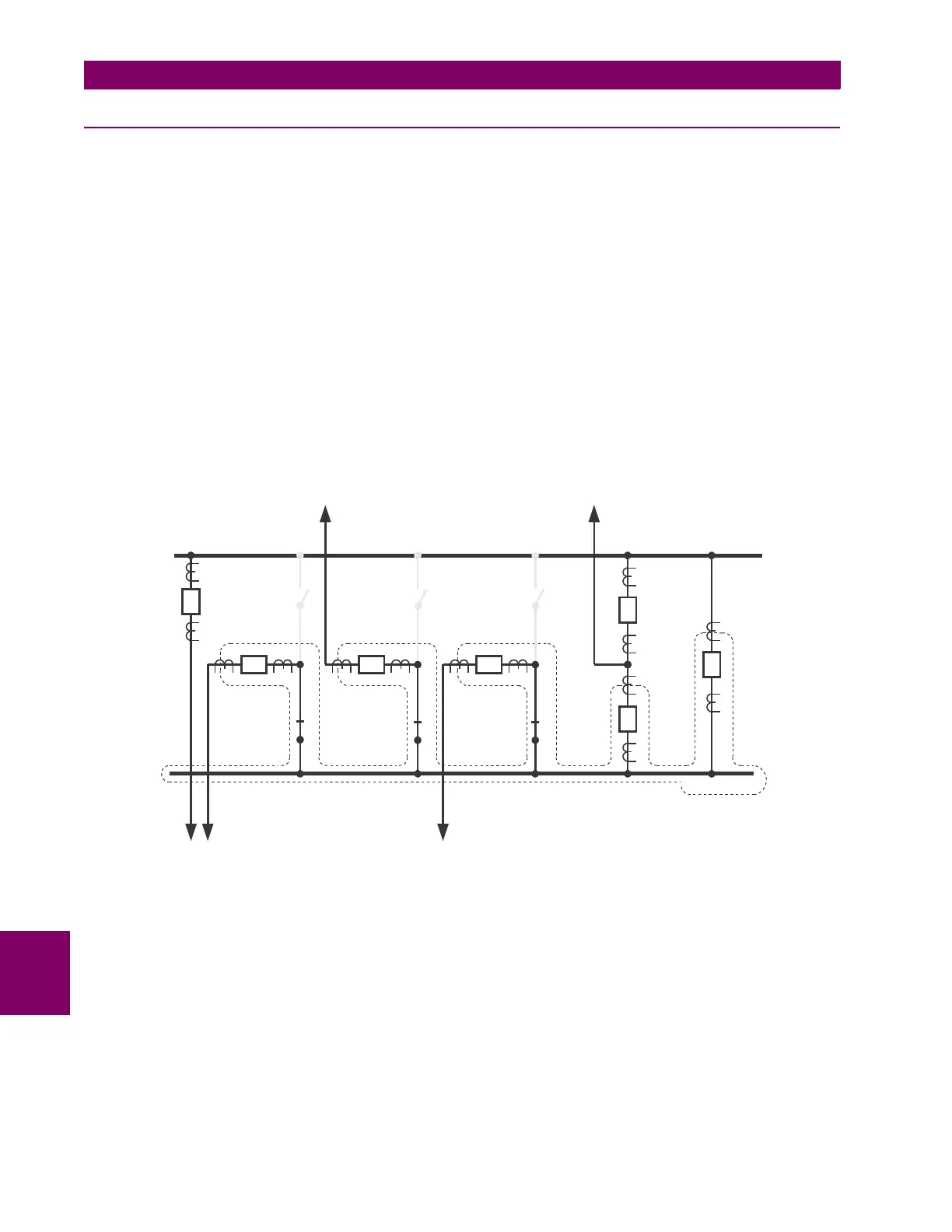
9.2.3 SOUTH BUS ZONE
The South bus differential zone is bounded by the following CTs: CT-2 (if S-2 closed), CT-3 (if S-4 closed), CT-4 (if S-6
closed), CT-6 and CT-7. The South bus protection should operate the following breakers: B-2 (if S-2 closed), B-3 (if S-4
closed), B-4 (if S-6 closed), B-6 and B-7.
Consequently, the second B30 for the South bus should be wired and configured as follows:
• CT-2 currents should be configured as SRC 1 and used as the source 1A of the bus differential zone 1 together with
the status of the S-2 switch.
• CT-3 currents should be configured as SRC 2 and used as the source 1B of the bus differential zone 1 together with
the status of the S-4 switch.
• CT-4 currents should be configured as SRC 3 and used as the source 1C of the bus differential zone 1 together with
the status of the S-6 switch.
• CT-6 currents should be configured as SRC 4 and used as the source 1D of the bus differential zone 1 together with
the FlexLogic “On” constant for the status.
• CT-7 currents should be configured as SRC 5 and used as the source 1E of the bus differential zone 1 together with
the FlexLogic “On” constant for the status.
• The trip signal should be routed directly to the B-6 and B-7 breakers while it should be supervised by the status of S-2,
S-4 and S-6 for the B-2, B-3 and B-4 breakers, respectively.
Figure 9–4: SOUTH BUS ZONE
836734A1.CDR
NORTH BUS
SOUTH BUS
CT-7
CT-8
B-7
B-5
B-6
CT-5
CT-6
S-5
S-6
B-4CT-4
S-3
S-4
B-3CT-3
S-1
S-2
B-2CT-2
CT-1
B-1
C-1 C-2 C-4
C-3 C-5